Download
1 / 24
260 likes | 399 Views
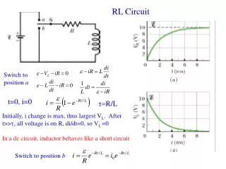
First Order RL and RC Circuit. 7.1-7.4,7.5, 7.7. Natural Response. Definition : The currents and voltages that arise when stored energy in an inductor or capacitor is suddenly released to a resistive network. RL Circuit. The switch opens at t=1S. Switch Setting. The switch opens at t=1.

E N D
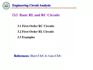
First Order RL and RC Circuit 7.1-7.4,7.5, 7.7
Natural Response • Definition: The currents and voltages that arise when stored energy in an inductor or capacitor is suddenly released to a resistive network
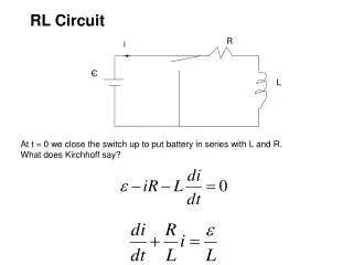
RL Circuit The switch opens at t=1S
Switch Setting The switch opens at t=1 Name of switch: sw_topen ROPEN=1 Mohms RCLOSE=0.01 Ohms
Transient Simulation Run a transient simulation from 0 to 10 s
Simulation Results For t<1S, current (1A) flow through L1, generating a VIN and VOUT=0. At t=1S, the current through L1 is 1A, so Vout=1V. At t>1S, VIN=-1V. What if you increase R2 by 10 times?
R2=1 Ohms R2=10 Ohms
L/R Constant • The rate that Vout drops to zero is related to L/R time constant. • The smaller the L/R time constant, the faster Vout drops to 0. • R2=10Ohms results in a circuit that drops to zero faster than R2=1 Ohm
Natural Response of RC Circuit C1 is charged until about t=2. C1 starts to charge at t=5.
Simulation Results VX=Vout after t=5! VX does not discharge between t=2-5S.
Step Response • Definition: The currents and voltages that arise when energy is being acquired by an inductor or capacitor due to the sudden application of dc voltage or current source.
Vout & Vin t‘=0
Step Response of an RC Circuit Note that the voltage across the capacitor is initially zero because Q can not change instantaneously.
C=1 F V=Q/C C=2 F
Experiment 1 (Large) No Voltage divider
Experiment 2 (change to 3) (Takes longer go charge, Less current is available)
R5 At DC, the op-amp is not able to provide feedback. Thus V- is not equal to V+. A resistor should be added in parallel of C1 so as to provide feedback at DC.
Select value of R5 This term should be minimized.
Choice of R5 R5=330 Kohms C1=92 nF R5=1 Kohms C1=92 nF