Download
1 / 73
730 likes | 991 Views
Sequential Logic Implementation. Sequential Circuits Primitive sequential elements Combinational logic Models for representing sequential circuits Finite-state machines (Moore and Mealy) Representation of memory (states) Changes in state (transitions) Basic sequential circuits

E N D
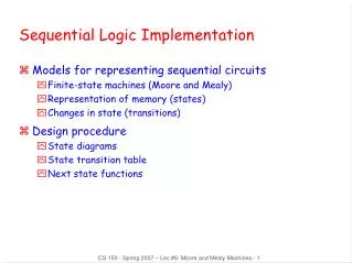
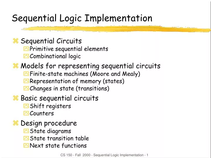
Sequential Logic Implementation • Sequential Circuits • Primitive sequential elements • Combinational logic • Models for representing sequential circuits • Finite-state machines (Moore and Mealy) • Representation of memory (states) • Changes in state (transitions) • Basic sequential circuits • Shift registers • Counters • Design procedure • State diagrams • State transition table • Next state functions CS 150 - Fall 2000 - Sequential Logic Implementation - 1
CombinationalLogic Inputs Outputs State Inputs State Outputs Storage Elements Abstraction of State Elements • Divide circuit into combinational logic and state • Localize feedback loops and make it easy to break cycles • Implementation of storage elements leads to various forms of sequential logic CS 150 - Fall 2000 - Sequential Logic Implementation - 2
Clock Forms of Sequential Logic • Asynchronous sequential logic – state changes occur whenever state inputs change (elements may be simple wires or delay elements) • Synchronous sequential logic – state changes occur in lock step across all storage elements (using a periodic waveform - the clock) CS 150 - Fall 2000 - Sequential Logic Implementation - 3
010 111 001 In = 1 In = 0 In = 0 100 110 In = 1 Finite State Machine Representations • States: determined by possible values in sequential storage elements • Transitions: change of state • Clock: controls when state can change by controlling storage elements • Sequential Logic • Sequences through a series of states • Based on sequence of values on input signals • Clock period defines elements of sequence CS 150 - Fall 2000 - Sequential Logic Implementation - 4
ERR closed not equal& new not equal& new not equal& new S3 S1 S2 OPEN closed mux=C1 closed mux=C2 closed mux=C3 reset open equal& new equal& new equal& new not new not new not new Example Finite State Machine Diagram • Combination lock from first lecture CS 150 - Fall 2000 - Sequential Logic Implementation - 5
OUT1 OUT2 OUT3 D Q D Q D Q IN CLK 110 100 1 0 1 1 1 010 101 111 000 1 1 0 1 0 0 001 011 1 0 0 0 0 Can Any Sequential System be Represented with a State Diagram? • Shift Register • Input value shownon transition arcs • Output values shownwithin state node CS 150 - Fall 2000 - Sequential Logic Implementation - 6
010 011 001 000 100 3-bit up-counter 110 101 111 Counters are Simple Finite State Machines • Counters • Proceed thru well-defined state sequence in response to enable • Many types of counters: binary, BCD, Gray-code • 3-bit up-counter: 000, 001, 010, 011, 100, 101, 110, 111, 000, ... • 3-bit down-counter: 111, 110, 101, 100, 011, 010, 001, 000, 111, ... CS 150 - Fall 2000 - Sequential Logic Implementation - 7
OUT1 OUT2 OUT3 D Q D Q D Q CLK "1" How Do We Turn a State Diagram into Logic? • Counter • Three flip-flops to hold state • Logic to compute next state • Clock signal controls when flip-flop memory can change • Wait long enough for combinational logic to compute new value • Don't wait too long as that is low performance CS 150 - Fall 2000 - Sequential Logic Implementation - 8
FSM Design Procedure • Start with counters • Simple because output is just state • Simple because no choice of next state based on input • State diagram to state transition table • Tabular form of state diagram • Like a truth-table • State encoding • Decide on representation of states • For counters it is simple: just its value • Implementation • Flip-flop for each state bit • Combinational logic based on encoding CS 150 - Fall 2000 - Sequential Logic Implementation - 9
current state next state0 000 001 11 001 010 22 010 011 33 011 100 44 100 101 55 101 110 66 110 111 77 111 000 0 010 011 001 000 100 3-bit up-counter 110 101 111 FSM Design Procedure: State Diagram to Encoded State Transition Table • Tabular form of state diagram • Like a truth-table (specify output for all input combinations) • Encoding of states: easy for counters – just use value CS 150 - Fall 2000 - Sequential Logic Implementation - 10
C3 C3 C3 0 1 1 0 1 1 0 0 0 0 0 1 1 0 0 1 1 1 0 0 1 1 0 1 C1 C1 C1 C2 C2 C2 C3 C2 C1 N3 N2 N10 0 0 0 0 10 0 1 0 1 00 1 0 0 1 10 1 1 1 0 01 0 0 1 0 11 0 1 1 1 01 1 0 1 1 11 1 1 0 0 0 N3 N1 N2 Implementation • D flip-flop for each state bit • Combinational logic based on encoding notation to show function represent input to D-FF N1 := C1' N2 := C1C2' + C1'C2 := C1 xor C2 N3 := C1C2C3' + C1'C3 + C2'C3 := C1C2C3' + (C1' + C2')C3 := (C1C2) xor C3 CS 150 - Fall 2000 - Sequential Logic Implementation - 11
D Q Q Implementation (cont'd) • Programmable Logic Building Block for Sequential Logic • Macro-cell: FF + logic • D-FF • Two-level logic capability like PAL (e.g., 8 product terms) CS 150 - Fall 2000 - Sequential Logic Implementation - 12
In C1 C2 C3 N1 N2 N30 0 0 0 0 0 00 0 0 1 0 0 00 0 1 0 0 0 10 0 1 1 0 0 10 1 0 0 0 1 00 1 0 1 0 1 00 1 1 0 0 1 10 1 1 1 0 1 11 0 0 0 1 0 01 0 0 1 1 0 01 0 1 0 1 0 11 0 1 1 1 0 11 1 0 0 1 1 01 1 0 1 1 1 01 1 1 0 1 1 11 1 1 1 1 1 1In C1 C2 C3 N1 N2 N30 0 0 0 0 0 00 0 0 1 0 0 00 0 1 0 0 0 10 0 1 1 0 0 10 1 0 0 0 1 00 1 0 1 0 1 00 1 1 0 0 1 10 1 1 1 0 1 11 0 0 0 1 0 01 0 0 1 1 0 01 0 1 0 1 0 11 0 1 1 1 0 11 1 0 0 1 1 01 1 0 1 1 1 01 1 1 0 1 1 11 1 1 1 1 1 1 OUT1 OUT2 OUT3 D Q D Q D Q IN CLK 110 100 1 0 1 1 1 010 101 111 1 000 1 0 1 0 0 001 011 1 0 0 0 0 Another Example • Shift Register • Input determines next state N1 := In N2 := C1 N3 := C2 CS 150 - Fall 2000 - Sequential Logic Implementation - 13
000 110 010 101 Present State Next State C B A C+ B+ A+ 0 0 0 0 1 0 0 0 1 – – – 0 1 0 0 1 1 0 1 1 1 0 1 1 0 0 – – – 1 0 1 1 1 0 1 1 0 0 0 0 1 1 1 – – – 011 More Complex Counter Example • Complex Counter • Repeats five states in sequence • Not a binary number representation • Step 1: Derive the state transition diagram • Count sequence: 000, 010, 011, 101, 110 • Step 2: Derive the state transition table from the state transition diagram note the don't care conditions that arise from the unused state codes CS 150 - Fall 2000 - Sequential Logic Implementation - 14
C C C 1 1 X 0 0 0 X 1 0 1 X 1 0 X X 0 0 X X 1 0 X X 1 A A A B B B A+ C+ B+ More Complex Counter Example (cont’d) • Step 3: K-maps for Next State Functions C+ := A B+ := B' + A'C' A+ := BC' CS 150 - Fall 2000 - Sequential Logic Implementation - 15
C C C 0 0 1 1 0 1 0 1 1 1 1 0 0 0 0 0 0 0 1 1 0 1 0 1 A A A B B B 111 001 000 110 100 010 101 011 Present State Next State C B A C+ B+ A+ 0 0 0 0 1 0 0 0 1 1 1 0 0 1 0 0 1 1 0 1 1 1 0 1 1 0 0 0 1 0 1 0 1 1 1 0 1 1 0 0 0 0 1 1 1 1 0 0 B+ C+ A+ Self-Starting Counters (cont’d) • Re-deriving state transition table from don't care assignment CS 150 - Fall 2000 - Sequential Logic Implementation - 16
111 001 000 110 100 010 101 implementation on previous slide 011 111 001 000 110 100 010 101 011 Self-Starting Counters • Start-up States • At power-up, counter may be in an unused or invalid state • Designer must guarantee it (eventually) enters a valid state • Self-starting Solution • Design counter so that invalid states eventually transition to a valid state • May limit exploitation of don't cares CS 150 - Fall 2000 - Sequential Logic Implementation - 17
outputlogic Outputs Inputs next statelogic Next State Current State State Machine Model • Values stored in registers represent the state of the circuit • Combinational logic computes: • Next state • Function of current state and inputs • Outputs • Function of current state and inputs (Mealy machine) • Function of current state only (Moore machine) CS 150 - Fall 2000 - Sequential Logic Implementation - 18
outputlogic Outputs Inputs next statelogic Next State Next State State Current State 0 1 2 3 4 5 Clock State Machine Model (cont’d) • States: S1, S2, ..., Sk • Inputs: I1, I2, ..., Im • Outputs: O1, O2, ..., On • Transition function: Fs(Si, Ij) • Output function: Fo(Si) or Fo(Si, Ij) CS 150 - Fall 2000 - Sequential Logic Implementation - 19
Example: Ant Brain (Ward, MIT) • Sensors: L and R antennae, 1 if in touching wall • Actuators: F - forward step, TL/TR - turn left/right slightly • Goal: find way out of maze • Strategy: keep the wall on the right CS 150 - Fall 2000 - Sequential Logic Implementation - 20
Ant Behavior B: Following wall, not touching Go forward, turning right slightly A: Following wall, touching Go forward, turning left slightly D: Hit wall again Back to state A C: Break in wall Go forward, turning right slightly E: Wall in front Turn left until... F: ...we are here, same as state B G: Turn left until... LOST: Forward until we touch something CS 150 - Fall 2000 - Sequential Logic Implementation - 21
L + R L’ R LOST (F) E/G(TL) A (TL, F) L + R L R L’ R’ L’ R’ R L’ R’ B (TR, F) C(TR, F) R’ R’ Designing an Ant Brain • State Diagram CS 150 - Fall 2000 - Sequential Logic Implementation - 22
Synthesizing the Ant Brain Circuit • Encode States Using a Set of State Variables • Arbitrary choice - may affect cost, speed • Use Transition Truth Table • Define next state function for each state variable • Define output function for each output • Implement next state and output functions using combinational logic • 2-level logic (ROM/PLA/PAL) • Multi-level logic • Next state and output functions can be optimized together CS 150 - Fall 2000 - Sequential Logic Implementation - 23
L + R L’ R state L R next state outputs LOST 0 0 LOST F LOST – 1 E/G F LOST 1 – E/G F A 0 0 B TL, F A 0 1 A TL, F A 1 – E/G TL, F B – 0 C TR, F B – 1 A TR, F ... ... ... ... ... LOST (F) E/G(TL) A (TL, F) L + R L R L’ R’ L’ R’ R L’ R’ B (TR, F) C(TR, F) R’ R’ Transition Truth Table • Using symbolic statesand outputs CS 150 - Fall 2000 - Sequential Logic Implementation - 24
Synthesis • 5 states : at least 3 state variables required (X, Y, Z) • State assignment (in this case, arbitrarily chosen) LOST - 000 E/G - 001 A - 010 B - 011 C - 100 state L R next state outputs X,Y,Z X', Y', Z' F TR TL 0 0 0 0 0 0 0 0 1 0 0 0 0 0 0 1 0 0 1 1 0 0 ... ... ... ... ... 0 1 0 0 0 0 1 1 1 0 1 0 1 0 0 1 0 1 0 1 0 1 0 1 0 1 0 0 0 1 1 0 1 0 1 0 1 1 0 0 1 1 0 1 0 1 1 0 0 1 0 0 1 1 0 0 1 1 0 1 0 1 0 1 1 0 ... ... ... ... ... it now remainsto synthesizethese 6 functions CS 150 - Fall 2000 - Sequential Logic Implementation - 25
Synthesis of Next State and Output Functions state inputs next state outputs X,Y,Z L R X+,Y+,Z+ F TR TL 0 0 0 0 0 0 0 0 1 0 0 0 0 0 - 1 0 0 1 1 0 0 0 0 0 1 - 0 0 1 1 0 0 0 0 1 0 0 0 1 1 0 0 1 0 0 1 - 1 0 1 0 0 0 1 0 0 1 1 - 0 1 0 0 0 1 0 1 0 0 0 0 1 1 1 0 1 0 1 0 0 1 0 1 0 1 0 1 0 1 0 1 - 0 0 1 1 0 1 0 1 1 - 0 1 0 0 1 1 0 0 1 1 - 1 0 1 0 1 1 0 1 0 0 - 0 1 0 0 1 1 0 1 0 0 - 1 0 1 0 1 1 0 e.g. TR = X + Y Z X+ = X R’ + Y Z R’ = R’ TR CS 150 - Fall 2000 - Sequential Logic Implementation - 26
F TR TL outputlogic next statelogic Next State L R X+ Y+ Z+ Current State X Y Z Circuit Implementation • Outputs are a function of the current state only - Moore machine CS 150 - Fall 2000 - Sequential Logic Implementation - 27
L’ R’ L + R L’ R 000 (F) 001(TL) 010 (TL, F) L + R L 101 R L’ R’ R L’ R’ 011 (TR, F) 100(TR, F) 110 R’ 111 R’ Don’t Cares in FSM Synthesis • What happens to the "unused" states (101, 110, 111)? • Exploited as don't cares to minimize the logic • If states can't happen, then don't care what the functions do • if states do happen, we may be in trouble Ant is in deep trouble if it gets in this state CS 150 - Fall 2000 - Sequential Logic Implementation - 28
State Minimization • Fewer states may mean fewer state variables • High-level synthesis may generate many redundant states • Two state are equivalent if they are impossible to distinguish from the outputs of the FSM, i. e., for any input sequence the outputs are the same • Two conditions for two states to be equivalent: • 1) Output must be the same in both states • 2) Must transition to equivalent states for all input combinations CS 150 - Fall 2000 - Sequential Logic Implementation - 29
L + R L’ R LOST (F) E/G(TL) A (TL, F) L + R L R L’ R’ L’ R’ R L’ R’ B (TR, F) C(TR, F) R’ R’ Ant Brain Revisited • Any equivalent states? CS 150 - Fall 2000 - Sequential Logic Implementation - 30
L + R L’ R LOST (F) E/G(TL) A (TL, F) L + R L R L’ R’ L’ R’ L’ R’ B/C (TR, F) R’ New Improved Brain • Merge equivalent B and C states • Behavior is exactly the same as the 5-state brain • We now need only 2 state variables rather than 3 CS 150 - Fall 2000 - Sequential Logic Implementation - 31
state inputs next state outputs X,Y L R X',Y' F TR TL 0 0 0 0 0 0 1 0 0 0 0 - 1 0 1 1 0 0 0 0 1 - 0 1 1 0 0 0 1 0 0 1 1 0 0 1 0 1 - 1 0 1 0 0 1 0 1 1 - 0 1 0 0 1 1 0 0 0 1 1 1 0 1 1 0 0 1 1 0 1 0 1 1 0 1 - 0 1 1 0 1 1 1 - 0 1 1 1 1 0 1 1 - 1 1 0 1 1 0 X X X X X TR Y+ TL X+ F 0 1 0 1 0 1 0 1 0 1 0 1 0 1 0 1 0 1 1 1 0 0 1 1 0 0 1 0 0 0 1 0 0 0 1 0 0 0 1 0 0 0 1 0 0 0 1 0 0 1 1 1 1 0 0 0 1 0 0 1 1 0 1 1 1 0 1 1 1 0 1 1 1 0 1 1 1 0 1 1 R R R R R L L L L L Y Y Y Y Y New Brain Implementation CS 150 - Fall 2000 - Sequential Logic Implementation - 32
L’ R / TL, F A L / TL L’ R’ / TR, F Mealy vs. Moore Machines • Moore: outputs depend on current state only • Mealy: outputs depend on current state and inputs • Ant brain is a Moore Machine • Output does not react immediately to input change • We could have specified a Mealy FSM • Outputs have immediate reaction to inputs • As inputs change, so does next state, doesn’t commit until clocking event react right away to leaving the wall CS 150 - Fall 2000 - Sequential Logic Implementation - 33
0 1 D/1 B/0 0 0 reset 1 0 A/0 1 1 E/1 C/0 0 1 Specifying Outputs for a Moore Machine • Output is only function of state • Specify in state bubble in state diagram • Example: sequence detector for 01 or 10 current next reset input state state output 1 – – A 0 0 A B 0 0 1 A C 0 0 0 B B 0 0 1 B D 0 0 0 C E 0 0 1 C C 0 0 0 D E 1 0 1 D C 1 0 0 E B 1 0 1 E D 1 CS 150 - Fall 2000 - Sequential Logic Implementation - 34
0/0 B 0/0 reset/0 0/1 1/1 A 1/0 C 1/0 Specifying Outputs for a Mealy Machine • Output is function of state and inputs • Specify output on transition arc between states • Example: sequence detector for 01 or 10 current next reset input state state output 1 – – A 0 0 0 A B 0 0 1 A C 0 0 0 B B 0 0 1 B C 1 0 0 C B 1 0 1 C C 0 CS 150 - Fall 2000 - Sequential Logic Implementation - 35
logic foroutputs inputs inputs outputs combinational logic for next state combinational logic fornext state logic foroutputs reg reg outputs state feedback state feedback Comparison of Mealy and Moore Machines • Mealy Machines tend to have less states • Different outputs on arcs (n^2) rather than states (n) • Moore Machines are safer to use • Outputs change at clock edge (always one cycle later) • In Mealy machines, input change can cause output change as soon as logic is done – a big problem when two machines are interconnected – asynchronous feedback • Mealy Machines react faster to inputs • React in same cycle – don't need to wait for clock • In Moore machines, more logic may be necessary to decode state into outputs – more gate delays after CS 150 - Fall 2000 - Sequential Logic Implementation - 36
Mealy and Moore Examples • Recognize A,B = 0,1 • Mealy or Moore? CS 150 - Fall 2000 - Sequential Logic Implementation - 37
Mealy and Moore Examples (cont’d) • Recognize A,B = 1,0 then 0,1 • Mealy or Moore? CS 150 - Fall 2000 - Sequential Logic Implementation - 38
Registered Mealy Machine (Really Moore) • Synchronous (or registered) Mealy Machine • Registered state AND outputs • Avoids ‘glitchy’ outputs • Easy to implement in PLDs • Moore Machine with no output decoding • Outputs computed on transition to next state rather than after entering • View outputs as expanded state vector outputlogic Outputs Inputs next statelogic Current State CS 150 - Fall 2000 - Sequential Logic Implementation - 39
Example: Vending Machine • Release item after 15 cents are deposited • Single coin slot for dimes, nickels • No change Reset N VendingMachineFSM Open CoinSensor ReleaseMechanism D Clock CS 150 - Fall 2000 - Sequential Logic Implementation - 40
Reset S0 N D S1 S2 N D N D S3 S4 [open] S5 [open] S6 [open] N S7 [open] Example: Vending Machine (cont’d) • Suitable Abstract Representation • Tabulate typical input sequences: • 3 nickels • nickel, dime • dime, nickel • two dimes • Draw state diagram: • Inputs: N, D, reset • Output: open chute • Assumptions: • Assume N and D assertedfor one cycle • Each state has a self loopfor N = D = 0 (no coin) CS 150 - Fall 2000 - Sequential Logic Implementation - 41
present inputs next outputstate D N state open 0¢ 0 0 0¢ 0 0 1 5¢ 0 1 0 10¢ 0 1 1 – – 5¢ 0 0 5¢ 0 0 1 10¢ 0 1 0 15¢ 0 1 1 – –10¢ 0 0 10¢ 0 0 1 15¢ 0 1 0 15¢ 0 1 1 – –15¢ – – 15¢ 1 Reset 0¢ N 5¢ D N 10¢ D N + D 15¢ [open] symbolic state table Example: Vending Machine (cont’d) • Minimize number of states - reuse states whenever possible CS 150 - Fall 2000 - Sequential Logic Implementation - 42
Example: Vending Machine (cont’d) • Uniquely Encode States present state inputs next state output Q1 Q0 D N D1 D0 open 0 0 0 0 0 0 0 0 1 0 1 0 1 0 1 0 0 1 1 – – – 0 1 0 0 0 1 0 0 1 1 0 0 1 0 1 1 0 1 1 – – – 1 0 0 0 1 0 0 0 1 1 1 0 1 0 1 1 0 1 1 – – – 1 1 – – 1 1 1 CS 150 - Fall 2000 - Sequential Logic Implementation - 43
Q1 Q1 Q1 Open D1 D0 0 1 1 0 1 0 1 1 X X X X 0 1 1 1 0 0 1 0 0 0 1 0 X X X X 0 0 1 0 0 0 1 1 0 1 1 1 X X X X 1 1 1 1 N N N D D D Q0 Q0 Q0 Example: Vending Machine (cont’d) • Mapping to Logic D1 = Q1 + D + Q0 N D0 = Q0’ N + Q0 N’ + Q1 N + Q1 D OPEN = Q1 Q0 CS 150 - Fall 2000 - Sequential Logic Implementation - 44
Example: Vending Machine (cont’d) • One-hot Encoding present state inputs next state outputQ3 Q2 Q1 Q0 D N D3 D2 D1 D0 open 0 0 0 1 0 0 0 0 0 1 0 0 1 0 0 1 0 0 1 0 0 1 0 0 0 1 1 - - - - - 0 0 1 0 0 0 0 0 1 0 0 0 1 0 1 0 0 0 1 0 1 0 0 0 0 1 1 - - - - - 0 1 0 0 0 0 0 1 0 0 0 0 1 1 0 0 0 0 1 0 1 0 0 0 0 1 1 - - - - - 1 0 0 0 - - 1 0 0 0 1 D0 = Q0 D’ N’ D1 = Q0 N + Q1 D’ N’ D2 = Q0 D + Q1 N + Q2 D’ N’ D3 = Q1 D + Q2 D + Q2 N + Q3 OPEN = Q3 CS 150 - Fall 2000 - Sequential Logic Implementation - 45
N’ D’ + Reset (N’ D’ + Reset)/0 Reset Reset/0 0¢ [0] 0¢ N’ D’ N’ D’/0 N N/0 5¢ [0] 5¢ D D/0 N’ D’ N’ D’/0 N N/0 10¢ [0] 10¢ N’ D’ N’ D’/0 D D/1 N+D N+D/1 15¢ [1] 15¢ Reset’ Reset’/1 Equivalent Mealy and Moore State Diagrams • Mealy machine • outputs associated with transitions • Moore machine • outputs associated with state CS 150 - Fall 2000 - Sequential Logic Implementation - 46
Example: Traffic Light Controller • A busy highway is intersected by a little used farmroad • Detectors C sense the presence of cars waiting on the farmroad • with no car on farmroad, light remain green in highway direction • if vehicle on farmroad, highway lights go from Green to Yellow to Red, allowing the farmroad lights to become green • these stay green only as long as a farmroad car is detected but never longer than a set interval • when these are met, farm lights transition from Green to Yellow to Red, allowing highway to return to green • even if farmroad vehicles are waiting, highway gets at least a set interval as green • Assume you have an interval timer that generates: • a short time pulse (TS) and • a long time pulse (TL), • in response to a set (ST) signal. • TS is to be used for timing yellow lights and TL for green lights CS 150 - Fall 2000 - Sequential Logic Implementation - 47
Example: Traffic Light Controller (cont’) • Highway/farm road intersection farm road car sensors highway CS 150 - Fall 2000 - Sequential Logic Implementation - 48
Example: Traffic Light Controller (cont’) • Tabulation of Inputs and Outputsinputsdescriptionoutputsdescriptionreset place FSM in initial state HG, HY, HR assert green/yellow/red highway lightsC detect vehicle on the farm road FG, FY, FR assert green/yellow/red highway lightsTS short time interval expired ST start timing a short or long intervalTL long time interval expired • Tabulation of unique states – some light configurations imply othersstatedescriptionS0 highway green (farm road red)S1 highway yellow (farm road red)S2 farm road green (highway red)S3 farm road yellow (highway red) CS 150 - Fall 2000 - Sequential Logic Implementation - 49
Reset (TL•C)' S0 TL•C / ST TS / ST S1 S3 TS' TS' TS / ST TL+C' / ST S2 (TL+C')' Example: Traffic Light Controller (cont’) • State Diagram S0: HG S1: HY S2: FG S3: FY CS 150 - Fall 2000 - Sequential Logic Implementation - 50