Download
1 / 27
270 likes | 423 Views
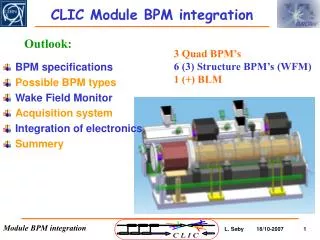
CTF3 module and CLIC Final Doublet stabilization. CERN, JAI, PSI, LAPP. Program. Concerns Instrumentation for 1nm at 1Hz (seismic sensors and interferometric measurement) CTF3 test environment Combine passive and active damping Active stabilisation for 0.1nm above 1Hz Conclusion. Concerns.

E N D
CTF3 module and CLIC Final Doublet stabilization CERN, JAI, PSI, LAPP
Program • Concerns • Instrumentation for 1nm at 1Hz (seismic sensors and interferometric measurement) • CTF3 test environment • Combine passive and active damping • Active stabilisation for 0.1nm above 1Hz • Conclusion
The CLIC luminosity performance critically depends on the main linac quadrupole vertical stability (<1nm @ 1Hz) and the final doublet stability (<0.1nm @ 4 Hz) in noisy site Linac 1.3nm S.Redaelli’s PhD 2003 FF 0.2nm Measurement of the quadrupole vibrations on active table in vertical direction compared to linac and Final Focus (FF) tolerances at 4Hz (in 2003) 4 Hz
At SLS at PSI, quad vs ground: some peaks correlate with beam jitter, some can be explained by He compressors or beam infrastructure (seen also in beam), but some peaks are due to girder resonances • Stable or damped support vital, but test in accelerator environment essential R.Assmann et al CERN-AB-2004-074
State of the art inertial sensors • NI PCI-6052 Multifunction DAQ Fast card Low noise card • Compatible Matlab/Simulink (Softwares used for the algorithm) nm stabilisation equipment exists
Mechanical design Original concept PZT PZT Input beam Parallel Michelson
Michelson : realised in the lab PZT swept mirror Stationary mirror Camera Beam-splitter Launch collimator
Why test in an accelerator environment? B.Bkalov et al PHY REV Spec Topics- Accel and beams 1 031001 (1998) Tevatron integrated rms in deep tunnel: at 0.1 Hz, 0.3micron and falls off with increasing frequency, there are strong peaks correlated with the beam frequency (magnet distortion during running cycle) below 5 Hz and above 20 Hz, the equipment in tunnel is noisier than surface at night. Also very strong correlation with He liquefier plant. In LEP tunnel, above 4 Hz, vibration goes from 0.2 nm to 20nm when beam equipment is turned on.(V.E.Balakin et al CERN-SL-93-30-RFL (1993). Ramila Amirikas and DESY team presented (at LCWS 07) some site measurements Fermilab surface 32 nm at 1Hz, CERN 22 nm at 1Hz Fermilab tunnel 3nm LHC tunnel 2nm Did some calculations to remove the 1/f and to keep only cultural noise: Quiet sites below 10nm, medium below 30nm, and noisy sites above 50nm.
1 nm at 1Hz test Quadrupole type 1module CLIC Standard module waveguide acc. structure DB Quad PETS supports MB quadrupole
1 nm at 1Hz test In CTF3 dedicated linac test-stand Accel. structure PETS
Advantages • Unique opportunity to correlate sensors and interferometer measurements • Opportunity to test the installation in accelerator environment
0.1 nm at 4Hz test • No dedicated site in CTF3 • Initial tests in Annecy • CLEX with accelerator environment • Mechanical measurement lab (not a stable zone) • Work with survey to find a base-plate site (where alignment tests are made?) • LHC tunnel had been suggested, but difficult to access (soon…?) • Material: • “old” CERN/CLIC table (currently in Annecy) • or buy a new one with more accessible control • Sensor development • Install final focus magnet mock-up on test support • Use of different sensors compare with laser interferometer: reference on floor and measurement on mock-up
Active compensation The prototype • The large prototype and its instrumentation : 2.5 m long • Actuators used for the active control of vibration : • Force = 19.3 N • Maximal displacement = 27,8 μm • Resolution = 0,28 nm - A stacking of PZT patches -
Active compensation Another approach of the problem L.Brunetti • Test an intermediary solution : to control a larger bandwidth A local model of the process A local model of the process A complete model of the process A knowledge of the process at strategic points f0 f1 fi 1 - A complete model of the structure : too complex 2 - A knowledge of the structure at strategic points : the initially developed algorithm 3 - A local model of the structure : for the disturbances amplified by eigenfrequencies.
Active control CIM Tests with the large prototype • Results : integrated displacement RMS
Tests with the large prototype: quiet room integrated displacement RMS (with active table ON) 1 nm Actuator electronic noise at 50 Hz
FD stability Things we don’t know: What is the FD configuration? Saclay? Is it normal or superconducting? (M.Aleksa’s work: Sm2Co17) How close to detector? MDI issues=> free-fixed or fixed-fixed configuration? Simulations for different configurations: Free, free-fixed… 1 support, multi-support…
Active isolation The small and elementary mock-up • Association of active and passive isolation : • The passive layer : Require active isolation Δf Passive isolation is efficient Resonantfrequency of the rubber Not heavy enough to use industrial products, but it is possible with a larger prototype.
Test stand at PSI (within XFEL) passive damping with some active compensation with stepping motors Stepping motors Passive damping material: possibly polyurethane Adjustment feet
Procurement • Module test: • Sensors and DAQ: Annecy • Interferometric measurements: Oxford • Module and support: CERN • Alternative support: PSI • 0.1nm on Final focus: • Feedback: Annecy • Support: “old” table CERN/Annecy • FF mock-up: Annecy • Sensor development: CERN?
Ending comments • Financing? Within FP7 framework? And local institutions • Personnel issues • See how it interferes with the alignment system (close discussion with Hélène). • Follow CTF3 module development