Download
1 / 15
150 likes | 244 Views
AWAKE Electron Spectrometer Design. Simon Jolly 4 th September 2012. Spectrometer Specifications. Wakefield accelerated electrons ejected colinear with proton beam: need to separate the 2 and measure energy of electron beam only.

E N D
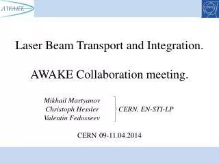
AWAKE Electron Spectrometer Design Simon Jolly 4th September 2012
Spectrometer Specifications • Wakefield accelerated electrons ejected colinear with proton beam: need to separate the 2 and measure energy of electron beam only. • Must be able to resolve energy spread as well as energy: spectrometer must accept a range of energies, probably 0-5 GeV. • Simple conceptual layout: • Dipole mounted at plasma exit separates proton and electron beams. • Scintillator screen 4 m downstream of dipole intercepts electron beam ONLY. • Dispersion gives energy-dependent position spread on screen. • Scintillator imaged by intensified CCD camera viewing upstream face of scintillator screen. Simon Jolly, University College London
Spectrometer Layout Dipole separates protons from electrons AND puts energy-dependent spread in beam. Electrons intercepted by scintillator screen, imaged by high speed iCCD camera. Screen nominally 4 m from dipole. Dipole Electron beam Screen iCCD Camera Proton beam iCCD Image Low energy High energy Simon Jolly, University College London
Browne-Beuchner Spectrometer (Alexey) C. P. Browne and W. W. Buechner, Rev. Sci. Instrum. 27, 899 (1956). Focusing in broad energy range is achieved via pole face curvature. Removes angular convolution from energy measurement, but needs ~3 m magnet for 5 GeV at 1.5 T… Simon Jolly, University College London
Spectrometer Beam Trajectories (Alexey) Simon Jolly, University College London
With Quadrupole Doublet (Alexey) Simon Jolly, University College London
With Fringe Fields (Alexey) Simon Jolly, University College London
Proton Microbunches After Plasma (Alexey) 0 m after plasma Transverse Distributions -60 mm < s < -40 mm 2 m after plasma 6 m after plasma Simon Jolly, University College London
CERN 1 m Dipole (Edda, Alexey) Simon Jolly, University College London
AWAKE Spectrometer Layout • Edge of scintillator screen is aligned with dipole coils (position will depend on resolution). • Screen mounted at 45 degrees to beam axis. • Camera is 4m from centre of screen, mounted at 90 degrees to beam axis. • Camera shown in horizontal bending plane. • Camera can also be mounted vertically, directly above screen, with screen tilted at 45 degrees to vertical as well as 45 degrees to beam axis. Dipole to screen distance remains unchanged (independent of screen-camera orientation). Dipole 1.6 m Camera 1 m Screen 4 m Simon Jolly, University College London
AWAKE Spectrometer Layout 2 Dipole 1.6 m Camera Screen 2 m 1 m Simon Jolly, University College London
Layout Questions • Do we need 2 dipoles? • Difficult to get good low/high field from single dipole. • Weak dipole (Browne-Buechner?) upstream of strong dipole analyses 1-20 MeV electrons. • Reduces available longitudinal space, increases complexity: need 2nd screen & camera + larger vacuum vessel. • Can we include quadrupole doublet? • Alexey’s simulations show improvement in energy range on screen with doublet. • Is there enough longitudinal space? • How close should screen be to dipole? • Closer gives better range, less effect of emittance, higher light output. • Greater distance improves resolution, requires smaller dipole. • Probably needs to be closer due to low beam intensity, large energy spread. • Optimum camera location? • Camera not radiation hard (waiting on specs from manufacturer), so needs to be well shielded ie. far from beamline. • Intensifier enhances low light output from screen (single photon detection) but more light into camera gives better signal-to-noise ie. close to beamline. • Mount camera above beamline? Increases distance from beamline while reducing distance to screen. Simon Jolly, University College London
Spectrometer Camera • Camera already purchased. • Andor iStar 340T iCCD camera: • 2048 x 512 total pixels (1850 x 512 active with 25 mm intensifier). • 13.5 um pixels. • Gen-2 W-AGT P43 intensifier, gated at 7 ns. • Nikon F-mount lens mount. • 16-bit readout, 150 ke- pixel full well. • http://www.andor.com/scientific_cameras/istar_iccd_camera/340-intensified-sensor/ • Camera setup: • DAQ and control software. • Data analysis software to give online measurement of witness beam energy spectrum. • Mechanical design of camera support system for tests and installation in SPS tunnel (comes later). Simon Jolly, University College London
Scintillator Choices • Scintillator requirements: • High light output (very low intensity electron beam). • Radiation hard (survive proton beam?). • Vacuum safe (screen inside vacuum vessel). • Scintillator choices from 3 different fields: • Accelerators (survive higher current): • Al2O3 (“ruby” powder, used in LHC BTV). • YAG:Ce (high light output). • Quartz (very rad hard, low light output). • Detectors (high light output): • CdWO4/PbWO4/ZnWO4 (CMS ECal). • CsI(Tl) (very high light output, not rad hard). • BGO/LYSO (more rad hard for lower light). • Plastics (less rad hard, cheap). • Plasma Wakefield (large area): • Lanex (large screens, vacuum safe?) • P43/P46/P47 phosphors (x-ray phosphors). • Need highest number of photons per solid angle to give maximum screen-to-camera distance. • Manual lens probably means no zoom (prime lens), so resolution fixed by mechanical layout. Simon Jolly, University College London
Conclusions • Baseline design is evolving rapidly: this is good! • Looks like optimum will be 45 degree screen close to dipole: • Alexey’s simulations show energies already well separated at dipole exit. • Get as close to dipole exit as possible while still imaging whole screen (camera view not obscured by dipole yoke). • Light path needs to be absolutely light tight (light from plasma exit?) but not necessarily vacuum tight. • Need input on scintillators to know what possibilities are: • Why is Lanex never used in HEP? • Need specs on light output to set maximum camera-to-screen distance. • Spectrometer design will probably evolve from all constraints ie. beamline space, radiation, vacuum vessel, then optimised within those constraints. Simon Jolly, University College London