Download
1 / 24
240 likes | 344 Views
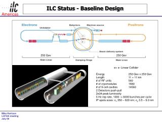
STATUS OF ILC ACTIVITY AT JINR. G. Shirkov Session of RAS, Protvino, December 22, 2008. GDE and ILCSC meetings at JINR, June 2008. Conclusions. We have presented the elements of the GDE plan for the next phase, which we call the Technical Design Phase.

E N D
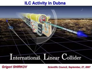
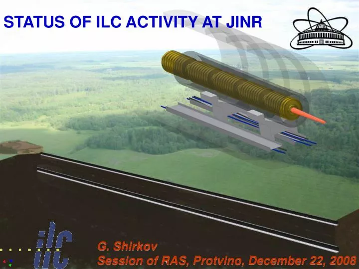
STATUS OF ILC ACTIVITY AT JINR G. Shirkov Session of RAS, Protvino, December 22, 2008
Conclusions • We have presented the elements of the GDE plan for the next phase, which we call the Technical Design Phase. • A two stage ILC Technical Design Phase (TDP I 2010 and TDP II 2012 is proposed) • Overall Goals: Cost reduction, technical design and implementation plan on the time scale of LHC results • SCIENCE remains the key to ultimate success(results at LCH).
Layout of ILC in the Moscow Region Tver region Moscow region
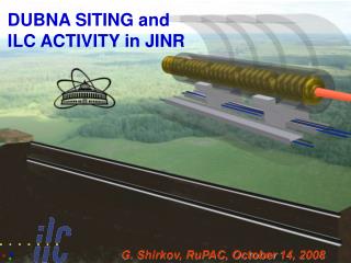
Dubna proposal: Shallow site with single tunnel buildings Vertical shaft Communication tunnel vertical communication shaft vertical shaft accelerator tunnel
A new suggested variant of the accelerator tunnel layout is under discussion and estimations now. It assumes the following: • main (beam) tunnel is located at approximately -20 m (at abs. level -100 m) in order to have impermeable layer above and below to be prevented from subsoil waters; • service (communication) tunnel is located directly above the main and around the earth surface (<-3-4 m), practically repeating the relief; • technological connection between two tunnels is provided with vertical shafts of different diameters, which are drilled with usual method; • connection between surface buildings and underground infrastructure is provided with vertical and horizontal shafts (elevators, stairs, etc) • cost of communication tunnel itself on the surface (without any equipment) is estimated by GSPI about 10 times cheaper in comparison with underground tunnel.
Service (communication) tunnel • Such a variant is more efficient economical by several reasons: • Service (communication) tunnel can have any size (section) for loading or filling the beam tunnel with any equipment, it is made by open-cut method; • Vertical connections are made by well-boring (relatively cheap method in comparison with case of horizontal ones), at the same time their number and sizes can be optimized. In addition – they do not require damp course; • Export of the drain waters is provided directly in accordance with relief, without any pumping stations; • Exploitation of the communication tunnels is sufficiently easier; • Cable and other technological connections between service tunnel with surface building is sufficiently reduced.
Geological investigations of GSPI in the Taldom region in October 2008 Hrabrovo Miakishevo GSPI has performed two drillings of chinks of 47 m and 43 m depth. The probes of soils are analyzing now. The power of loan are 27.5 m (2.0 m – 29.5 m) and 37.4 m (8.1 m – 45.5 m) correspondently. Geophysical investigations with a series of explosionshave been fulfilled as well.
Скважина 3 Скважина 1 Скважина 2 Космоснимоки районов расположения скважин 1, 2 и 3 (октябрь 2008)
The ILC linear accelerator is proposed to be placed in the drift clay at the depth of 20 m (at the mark of 100.00 m) with the idea that below the tunnel there should be impermeable soil preventing from the underlying groundwater inrush. It is possible to construct tunnels of the accelerating complex using tunnel shields with a simultaneous wall timbering by tubing or falsework concreting. Standard tunnel shields in the drift clay provide for daily speed of the drilling progress specified by the Project of the accelerator (it is needed approximately 2.5 years for the 50 km tunnel).
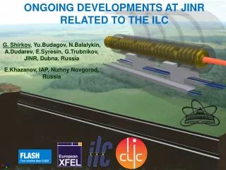
Participation of JINR in the ILC International Technical Activity International Linear Collider: accelerator physics and engineering • Theme leaders: A.N. Sissakian G.D. Shirkov • Period: 2007- 2009 • Preparation of works of JINR; • Participation in estimations • and design of ILC elements
JINR PARTICIPATION IN R&D OF ILC SUBSISTEMES AND IN RELATED PROJECTS 1. Construction of ILC photoinjector prototype. 2. The LINAC-800 based test-bench with electron beam 3. Development of power supply devices for RF system 4. Metrological laser complex 5. Development and design of cryogenic modules and test systems. 6. Preparation of technical base of cryogenic supply to test cryomodules of the 4th gen. 7. Calculation of electrical and magnetic fields 8. Engineering survey and design works 9. Development of the electron cooling method. LEPTA project. 10. Project CLIC 11. Project FLASH 12. Development of diagnostic systems; development of built-in devices. 13. Development of magnetic systems of the ILC damping rings 14. Development of diagnostics for large cryogenic systems. Personnel ~ 100 persons In total year 2007 ≈ 900 k$ (personnel 580 k$ + travels 90 k$ + R&D 230 k$)
Laser metrology JINR developed test bench at CERN for precise laser metrology. Results ofAug’06 0,5 micron precision of laser beam position measurement on the base of 40m is achieved. At JINR it is planned to set this complex at b.118 (base is 2x250m). DR magnetic system simulations and magnet prototype construction JINR in collaboration with SLAC works on design and possibility to construct at JINR workshop series of magnetic system elements of DR (few dipole magnets). It is also planned to provide test of those elements. This activity is performed in frames of MoU JINR-KEK on ATF collaboration. Similar MoU between JINR and SLAC is under assignment CLIC: Continuation of works with CERN: new prototype of the resonator was manufactured, proposed ways for increasing of the pulsed heating, results of the works on 2nd stage of the Contract approved by CERN. LINAC-800: Commissioning of the accelerating section (20-40 MeV) - 2008 Construction works at b.118, engineer infrustructure, modulator test bench, klystron test bench)
Linac-800 2004 2008 To the 1st FEL Injector : electron gun + chopper + pre-buncher. String test of the Sm-Co undulator magnetic field
JINR Participation in the ILC Cryomodule design. This international effort includes contributions from many institutions, including JINR together with FSUE “RFNC-VNIIEF” (Sarov, Russia). The key participants at the JINR are J.Budagov, B.Sabirov and A.Sukhanova. In the recent months JINR and Sarov have started a collaboration with INFN-Pisa on a bi-metallic Ti-SS transition tube to connect the Titanium helium vessel with a 76-mm diameter two-phase helium line in an ILC cryomodule (CM). Such a transition would allow for a very substantial cost savings in the ILC cryomodule production. Successful preliminary tests with prototype transition tubes of a smaller diameter, supplied by JINR and Sarov, were conducted by JINR in collaboration with INFN-Pisa.
Test results create a great impression at ILC Meeting in Florence. In the future the collaborative R&D of bi-metallic tubes for the ILC cryomodule and testing them should be done in conformance with the Technical Specifications. For more statistic a total of twenty tubes will then be delivered to Fermilab for further integration into a cryomodule. JINR with Sarov will carry out the work for production 10-20 units of the bi-metallic tubes will be sent consequently to the INFN/Pisa and FNAL following the schedule parties will agree timely. The tubes will be used at FNAL and in Pisa for ILC purposes.
Photo injector prototype activity - JINR scientists worked in operation runs at PITZ and FLASH. Several scientific missions of JINR staff to DESY Hamburg and Zoethen were done. - JINR performed design and started constructionofthe test bench for CsTe photocathode preparation. This test bench is planed to be used for preparation of GaAs photocathode in future.