Download
1 / 30
300 likes | 416 Views
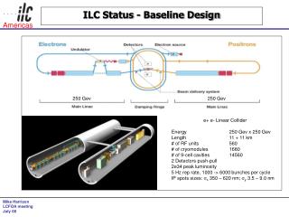
APPI 03/10/2005. Status of ILC Activity in KEK. H. Hayano, KEK. Official Time Schedule of ILC 2005.2 Decide the director and location of Central GDI 2005. Establish Regional GDIs 2005.8 Decide the design outline in Snowmass Workshop

E N D
APPI 03/10/2005 Status of ILC Activity in KEK H. Hayano, KEK
Official Time Schedule of ILC 2005.2 Decide the director and location of Central GDI 2005. Establish Regional GDIs 2005.8 Decide the design outline in Snowmass Workshop (acc.gradient, 1 or 2 tunnel, dogbone/small DR, e+generation etc) 2005 end CompleteCDR with rough cost/schedule 2007 end Complete TDR, role of regions, start site selection 2008 Decide the site, budget approval 2009 Ground breaking 2014 Commissioning starts
Asian Organization for ILC Research ●LC Office in Japan F. Takasaki, K. Yokoya, H. Hayano, N. Toge, S. Yamashita ●Working groups in Asian region WG1 Overall design (K. Kubo) WG2 Main Linac (H. Hayano) WG3 Injectors (M. Kuriki) WG4 Beam Delivery System (T. Sanuki) WG5 HG Cavities (K. Saito) ? Facility (A. Enomoto) ? Site (R. Sugawara)
Critical Research Areas ●Establishment of the technology for accelerating gradient 35MV/m . Technologies for cost reduction . Technologies for mass production ● Pursuit of possible higher accelerating gradient . Larger operational margin of gradient . Wider possibility of site selection ● Beam technology development using KEK-ATF . Unique storage ring to reach ILC emittance . Make full use of ATF capabilities
Guiding Principle Global Point of View ●Time line ●Low cost design ●Effective use of R&D budget by global coordination Regional Point of View ●Establish the leadership in leading areas ●Promote industrial level Time Scale ●Snowmass issues (Aug.2005) ●CDR issues (End of 2005) ●TDR issues (End of 2007)
Development of 45MV/m High Gradient Cavity ●Single-cell test in Dec 2004 - Mar 2005 ● Individual vertical test of four 9-cell cavities by Sep.2005 . Just in time for CDR completion . In existing facilities (AR east) . If expected performance not obtained, ⇒ change to slower plan for ILC 2nd stage ●Cryomodule test by end of 2006 ⇒ STF Phase 1 ● Industrial design by TDR
Superconducting RF Test Facility Comprehensive Test Facility dedicated to ILC SC-RF R&D 1. Superconducting Cavity; fabrication, surface treatment, installation, vertical test / horizontal test, system test with beam 2. Cryomodule; cavity installation, alignment, cryostat operation, heat cycle test, input coupler R&D, tuner mechanism R&D 3. Power source; modulator development, klystron development, WG components 4. He plant; High efficiency cryogenic system 5. Beam Instrumentation; ILC beam generation, BPM, HOM, Low-Level RF control 6. Cavity Surface Treatment Facility; BCP, CP, EP, HPR, clean room
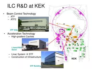
Location of Test Facilities STF KEK-B He Plant Control Center JPARC Proton Linac Building Will be empty in August 2005 Then, STF construction. ATF 1) 60m x 30m building: Klystron Gallery (with extendable space) Cavity installation room magnet power supply room (with extendable space) Control room (with extendable space) Cooling water facility AC power yard external Tent House 2) 5m x 3.85m x 93.5m tunnel: Access hatch only 2m x 4.5m with elevator (with extendable space) L-band R&D Stand #4 building
Purpose of STF ● Establish industrial design of Linac unit (35MV/m and 45MV/m) ●Promote Asian/Japanese industrial level for ILC component production ●Form Asian base for international collaboration ● Enlist/educate new comers
STF Phase 1 (2005-2006) ●Cryomodule for 4 45MV/m cavities ●Cryomodule for 4 35MV/m cavities ●RF source and cryogenic system (mostly recycled) ● Electron beam and its diagnostics system ●Synthetic test of 35MV/m & 45MV/m cryomodules with beam Other items in parallel ● Electro-polishing Facility . Can electro-polish cavities to be used overseas ●Cost reduction of cavity fabrication (Nb/Cu-clad, seamless)
STF Test Accelerator -------- phase 1 ------------------------ (RF gun): (1.3GHz 1.5cell copper cavity 42MV/m, 3.2nC/bunch 3.2MW, 1ms klystron, 5Hz) DC gun : DC 200kV CsTe photocathode for quick start + UV(262nm) Laser (337ns spacing, 2820bunches) Test Cryomodule : 4x 9cell TESLA SC cavity (5m cryomodule), 35MV/m 4x 9cell LL SC cavity (5m cryomodule), 45MV/m 4x 350kW + 4x 450kW = 3.2MW, 1.5ms klystron, 5Hz Beam analyzer: energy analyzer, emittance, BPM -------- phase 2 ------------------------ Accelerating Unit : 3 set of 17m full-size (12 cavities) cryomodule 2x 10MW, 1.5ms klystron, 5Hz
STF Infra-structure EP: build new EP(Electro chemical Polishing) facility HPR : move High Pressure Rinse from L-band test stand Clean room : build new clean room for cavity assemble Vertical Test Stand : build new stand, deep enough for superstructure cavity Coupler Test Stand : 5MW, 1.5ms klystron, 5Hz (switch use between Test Cryomodule ) He Plant : 600W at 4K plant moving from AR-East building (adding new 2K system )
Conceptual design of cryomodule STF Phase 1 Valve Box Why two module and connection? ->5m carry hatch, ->Establish weld connection in tunnel. Weld connection 35MV/m TESLA design cavities 45MV/m Low-loss cavities Become to 8 cavities in one cryostat Like TTF cryomodule
Preliminary design of cryomodulewhole assembly 35MV/m TESLA design cavities 45MV/m Low-loss cavities Single cryostat operation (option)
Cryomodule Cryostat Design KEK cryomodule cross-section Design is underway
STF Modulator, klystron plan 1.Buy 5MW Thales Klystron, Build Pulse trans, Modify PNC Modulator putting bouncer circuit in it. For driving cavities & Input coupler Test stand, later for RF-gun. PNC modulator TH2104C Additional PT+Bouncer circuit allows to use TH2104C. 2. Build one more modulator (ILC spec.) for cavity driving (in 2006). start investigation of technology for bouncer modulator/IGBT modulator.
STF Phase 2 (2007-2009) ●3 Cryomodules each containing 12 caviries (35 or 45MV/m) ●Reinforcement of RF and cryogenic systems ●Synthetic test with a beam Many uncertainties for Phase 2 ● GDI will be functional by the time of detail design of Phase 2 ● Collaboration/competition with TTF2/SMTF ● A few full-spec RF unit needed for TDR somewhere in the world ●STF Phase 2 is desired for Asian industrial level
ILC Cryomodule 1m dia. Cryostat(17m length), 12 of 9-cell SC Cavities
ATF ●Beam dynamics study (Fast ion instability, wiggler, etc) ●Development of diagnostics devices (Laser wire, cavity BPM etc.) ●Improvements of extracted beam (coupling, stabilization) ● Development and test of fast extraction kicker Extension of ATF Extraction Line : ATF2 (A) Small beam size (A1) Obtain σy ∼35nm (A2) Maintain for long time (B) Stabilization of beam center (B1) Down to <2nm by nanoBPM (cavity BPM) (B2) Bunch-to-bunch feedback of ILC-type beam (∼300ns interval)
ATF Mission: generation&confirmation of LC low emittance e- beam ATF emittance goal was set to X emit=2.5E-6( at 0 intensity) Y emit=2.5E-8( at 0 intensity) 1% from X
ATF2 : final focus beam line Line 1 or Line 2 (depend on movement plan of existing facility) ATF DR
International Collaboration on ATF2 ● Design study going on by international collaboration . Mini-workshops: Dec.11 at KEK, Jan. 5 at SLAC . Completion of optics design in ∼March ●Budget . Total 2.8 Oku Yen (floor, beamline, diagnostics) . Desirable to share the expenses among Asia, North America, Europe ●Present plan . Floor construction in summer 2006 . Start operation in Jan. 2007