Download
1 / 32
320 likes | 492 Views
Status of the ILC. Brian Foster (Oxford & GDE) PECFA Meeting CERN 27/11/09. Why the ILC?. I could pick many statements. Here are 2: CERN Council Strategy Document:

E N D
Status of the ILC Brian Foster (Oxford & GDE) PECFA Meeting CERN 27/11/09
Why the ILC? • I could pick many statements. Here are 2: • CERN Council Strategy Document: • “It is fundamental to complement the results of the LHC with measurements at a linear collider. In the energy range of 0.5 to 1 TeV, the ILC, based on superconducting technology, will provide an unique scientific opportunity at the energy frontier.” • OECD Science Ministerial Statement (2004)” • “..noted the worldwide consensus of the scientific community, which has chosen an electron-positron linear collider as the next accelerator-based facility… endorsed the OECD GSF statement on ILC….” Global Design Effort
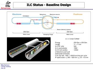
Why the ILC? • Ecm adjustable from 200 – 500 GeV • Luminosity ∫Ldt = 500 fb-1 in 4 years • (corresponds to 2*1034 cm-2 s-1 ) • Ability to scan between 200 and 500 GeV • Energy stability and precision below 0.1% • Electron polarization of at least 80% • The machine must be upgradeable to 1 TeV Global Design Effort
Overall ILC Layout from RDR 1st Stage: 500 GeV; central DR et al. campus; 2 “push-pull” detectors in 14 mrad IR. Global Design Effort
GDE Structure PAC ILCSC FALC FALC-RG Director’s Office = ~ Central Team = ~ EC + AAP ILC-GDE Director BB Regional Directors Project Managers Experts EC~11; weekly teleconf. CLIC PM • Project. M. Office • EDMS • Cost & Schedule • - Machine Detector Interface • - ILC, XFEL, Project X liaison • ILC Communications BF MH KY Global Design Effort
GDE R&D - the Technical Phase Updated every six months Global Design Effort Major TDP Goals: • ILC design evolved for cost / performance optimization • Complete crucial demonstration and risk-mitigating R&D • Updated VALUE estimate and schedule • Project Implementation Plan (PIP)
Available GDE resources Global Design Effort • Resource total: 2009-2012 • Not directly included: • There are other Project-specific and general infrastructure resources that overlap with ILC TDP
TDP Timeline TDR TDP Baseline Technical Design RDR Baseline TDP-1 TDP-2 Change Request New baseline inputs RDR ACD concepts R&D Demonstrations SB2009 studies 2009 2010 2011 2012 2013 Global Design Effort
Major R&D Goals for TDP1 • SCRF • High Gradient R&D - globally coordinated program to demonstrate gradient by 2010 with 50%yield • ATF-2 at KEK • Demonstrate Fast Kicker performance and Final Focus Design • Electron Cloud Mitigation – (CesrTA) • Electron Cloud tests at Cornell to establish mitigation and verify one damping ring is sufficient. • Accelerator Design and Integration (AD&I) • Studies of possible cost reduction designs and strategies for consideration in a re-baseline in 2010 Global Design Effort
SRF Test Facilities DESY KEK, Japan FNAL NML facility Under construction first beam 2010 ILC RF unit test STF (phase I & II) Under constructionfirst beam 2011 ILC RF unit test TTF/FLASH ~1 GeV ILC-like beam ILC RF unit(* lower gradient) Global Design Effort
Other Test Facilities ATF & ATF2 (KEK) ultra-low emittance Final Focus optics Cornell KEK, Japan INFN Frascati CesrTA (Cornell) electron cloud low emittance DAfNE (INFN Frascati) kicker development electron cloud Global Design Effort
Key R&D - SCRF Global Design Effort
Key R&D – SCRF Global Plan Global Design Effort
Key R&D – Cavity gradient • Two-pass processing of cavities • Yield at 31.5 MV/m ~40% Global Design Effort
Key R&D – 1st XFEL Cryomodule Global Design Effort
Key R&D – Cryomodule Global Design Effort
Key R&D – SCRF Future Strategy Global Design Effort
Key R&D – Beam Delivery Optical Table of the Shintake monitor • ATF2Goals • Test fast kicker magnet • Focus the electron beam to 35 nm in vertical • Stabilize the vertical beam position with 2 nm resolution ATF/ATF2Layout Global Design Effort
Key R&D – E cloud @ CESR Beampipe EM wave Low-energy electrons Phase velocitychangesin the ec region Signal Generator Receiver Bandpass Filter Amplifier Isolator 180º Hybrid Beam Electron Cloud Global Design Effort
Key R&D – CF&S & Rebaselining • Rationale to move away from RDR: Global Design Effort • Cost constraint in TDR • Updated cost estimate in 2012 6.7 BILCU • Need margin against possible increased component costs • Process forces critical review of RDR design • Errors and design issues identified • Iteration and refinement of design • More critical attention on difficult issues • Balance for risk-mitigating R&D • Majority of global resources focused in R&D • Important to prepare / re-focus project-orientated activities for TDP-2 • Need for design options and flexibility • Unknown site location
Key R&D – CF&S & Rebaselining • Proposals: • A Main Linac length consistent with an optimal choice of average accelerating gradient • RDR: 31.5 MV/m, to be re-evaluated • Single-tunnel solution for the Main Linacs and RTML, with two possible variants for the HLRF • Klystron cluster scheme • DRFS scheme • Undulator-based e+ source located at the end of the electron Main Linac (250 GeV) • Capture device: Quarter-wave transformer • Reduced parameter set (with respect to the RDR) • nb = 1312 (so-called “Low Power”) Global Design Effort
Key R&D – CF&S & Rebaselining • GDE group co-chaired by BF and A. Seryi tryingto answer questions from experiments on how these changes will affect physics extraction, backgrounds etc. Global Design Effort • Approx. 3.2 km circumference damping rings at5 GeV • 6 mm bunch length • Single-stage bunch compressor • compression factor of 20 • Integration of the e+ and e- sources into a common “central region beam tunnel”, together with the BDS.
Key R&D – CF&S & Rebaselining • RDR layout (not to scale) • SB2009 • layout • (not to • scale) Global Design Effort
Key R&D – RF Distribution • Klystron Cluster scheme: Global Design Effort
Key R&D – RF Distribution • Distributed scheme: Global Design Effort
Virtual ILC TOUR Electron Beam direction Positron Beam direction Central Integration – AD&I Transfer Tunnel branch Electron RTML (coming from DR) I.P. (down here somewhere) Positron Transfer Line Heading into DR Positron Main Dump line (after collision) BDS (e- side) Heading towards I.P. 8/28/2014 30/09/09 PAC Meeting, Pohang, Korea N.Collomb Global Design Effort
ILC-CLIC cooperation • CLIC – ILC Collaboration has two basic purposes: • allow a more efficient use of resources, especially engineers • CFS / CES • Beamline components (magnets, instrumentation…) • promote communication between the two project teams. • Comparative discussions and presentations will occur • Good understanding of each other’s technical issues is necessary • Communication network – at several levels – supports it • Seven working groups which are led by conveners from both projects Global Design Effort
ILC-CLIC cooperation • Conclusions from CERN/CLIC/ILC management at CERN include: • Existing workinggroups deemed success ; two more(damping rings & positron production) created • Jean Pierre Delahaye (CLIC StudyLeader) has joined GDE EC, and BF (European Regional Director) has joined the CLIC steering committee. • joint workshop in Sept/Oct. 2010; further joint management meetings. • Joint general issues subgroup endorsed by ILCSC and the CLIC Collaboration Board – joint chairs M. Harrison (GDE) & P. LeBrun (CLIC). Global Design Effort
ILC Governance & PIP ILCSC FALC Asian Governance GDE Governance American Governance ILCSC Siting ILC-HiGrade Governance CERN Council (Strategy group) Communication EU Legal Framework Cross-members Global Design Effort
ILC Governance timetable • 1) FALC presentation – July 13th 2009 ✔ • 2) Albuquerque Sep 29 – Oct 3 – tentative conclusion on funding model – fractions per partner, size of common fund etc. ✔ • 3) EC face-to-face ~ Jan. Oxford – conclusion on funding models, preliminary conclusion on governance model options • 4) Beijing March/April 2010? – conclusion on governance model options • 5) Write preliminary governance report and iterate May – June 2010 • 6) Present to and hope to get agreement from ICFA, ILCSC, PAC & FALC – June-July 2010? • 7) Present at Paris ICHEP July 2010 – N.B. this is not a final report and no funding authority/government will be expected to sign off on it. • ILC HiGrade Gov. meeting at lunchtime today on item 3) Global Design Effort
ILC Cost – fact & fiction • RDR cost (value) = 6.62 B$ (US 2007)(+ 24M person-hours explicit labor ~ $1.4B)=> $8B • So why do you keep hearing ludicrous figures like $20B? • DOE accounting - Add some contingency (note GDE estimates include some, but not all (DoE) contingency. It needs to be done item by item. (conservatively + 20%) • Escalation to “then year dollars” using arbitrary inflation estimate This is the big factor that people use – escalating for ~ 15-20 years gives ~ 200% • For the total project, this gives ~$20B+ (then year $$) • But e.g. Japan has ~ 0 inflation! • US will never build the entire machine • GDE aims that savings from rebaselining will maintain RDR cost in 2012 Global Design Effort
Summary and Outlook • Enormous progress continues to be made in ALL of • the critical R&D areas essential to build affordable ILC – • particularly in SCRF. • Wider political arena being addressed through ILCSC • and FALC. • On schedule for submission of convincing & detailed • TDR end 2012. • Next steps rebaselining meeting in DESY next week • and AAP review in Oxford Jan 6 - 8. • I hope to be able to report more progress to you at next PECFA meeting. Global Design Effort