Download
1 / 61
610 likes | 758 Views
Status of the ILC Accelerator Design. Barry Barish, Nick Walker for the entire ILC machine community 2 nd ILC Workshop – Snowmass, Colorado 26.08.2005. The Year After ‘Unification’. 1 st ILC workshop at KEK November 2005 ILCSC forms 5 technical WG + 1 communications and outreach WG

E N D
Status of the ILC Accelerator Design Barry Barish, Nick Walker for the entire ILC machine community 2nd ILC Workshop – Snowmass, Colorado 26.08.2005
The Year After ‘Unification’ • 1st ILC workshop at KEK November 2005 • ILCSC forms 5 technical WG + 1 communications and outreach WG • WG1 Parameters & General Layout • WG2 Main Linac • WG3 Injectors • WG4 Beam Delivery & MDI • WG5 High gradient SCRF • WG6 Communications Nick Walker - 2nd ILC Workshop - Snowmass - Colorado
The Year After ‘Unification’ Goals of the1st Workshop Nick Walker - 2nd ILC Workshop - Snowmass - Colorado
WG1 Parms & layout WG2 Linac WG3 Injectors WG4 Beam Delivery WG5 High Grad. SCRF WG6 Communications WG1 LET beam dynamics WG2 Main Linac WG3a Sources WG3b Damping Rings WG4 Beam Delivery WG5 SCRF Cavity Package WG6 Communications The Year After ‘Unification’ Birth of the GDE and Preparation for Snowmass Nick Walker - 2nd ILC Workshop - Snowmass - Colorado
WG1 Parms & layout WG2 Linac WG3 Injectors WG4 Beam Delivery WG5 High Grad. SCRF WG6 Communications WG1 LET beam dynamics WG2 Main Linac WG3a Sources WG3b Damping Rings WG4 Beam Delivery WG5 SCRF Cavity Package WG6 Communications GG1 Parameters & Layout GG2 Instrumentation GG3 Operations & Reliability GG4 Cost Engineering GG5 Conventional Facilities GG6 Physics Options The Year After ‘Unification’ Birth of the GDE and Preparation for Snowmass Introduction of Global Groups transition workshop → project Nick Walker - 2nd ILC Workshop - Snowmass - Colorado
WG1 LET bdyn. WG2 Main Linac WG3a Sources WG3b DR WG4 BDS WG5 Cavity GG1 Parameters GG2 Instrumentation GG3 Operations & Reliability GG4 Cost & Engineering GG5 Conventional Facilities GG6 Physics Options 2nd ILC Workshop (Snowmass) Technical sub-system WG Provide input Global Group Nick Walker - 2nd ILC Workshop - Snowmass - Colorado
Goals of the 2nd Workshop • Continue process of making a recommendation on aBaseline Configuration • Identify longer-termAlternative Configurations • Identify necessary R&D • For baseline • For alternatives • Priorities for detector R&D This workshop has been a major step towards these milestones Nick Walker - 2nd ILC Workshop - Snowmass - Colorado
Baseline / Alternative:some definitions • Primary GDE Goal: • Reference Design Report including costs end 2006 • Intermediate goal (follows from primary) • Definition of a Baseline Configurationby end of 2005 • Will be designed to during 2006 • Will be basis used for cost estimate • Will NOT be the machine we will build Nick Walker - 2nd ILC Workshop - Snowmass - Colorado
Baseline / Alternative:some definitions Baseline: a forward looking configuration which we are reasonably confident can achieve the required performanceand can be used to give a reasonably accurate cost estimate by mid-end 2006 (→ RDR) Nick Walker - 2nd ILC Workshop - Snowmass - Colorado
Baseline / Alternative:some definitions Alternate: A technology or concept which may provide a significant cost reduction, increase in performance (or both), but which will not be mature enough to be considered baseline by mid-end 2006Note:Alternatives will be part of the RDRAlternatives are equally important Nick Walker - 2nd ILC Workshop - Snowmass - Colorado
Baseline Configuration Document • Our ‘Deliverable’ by the end of 2005 • A structured electronic document • Documentation (reports, drawings etc) • Technical specs. • Parameter tables • … • A ‘printable / readable’ summary document (~100 pages) Nick Walker - 2nd ILC Workshop - Snowmass - Colorado
Structure of the BCD Summary-like overview for those who want to understand the choice and the why Technical documentation of the baseline, for engineers and acc. phys. making studies towards RDR Nick Walker - 2nd ILC Workshop - Snowmass - Colorado
Alternatives Section(s) Note ACD is part of the BCD Nick Walker - 2nd ILC Workshop - Snowmass - Colorado
The Hard Questions Nick Walker - 2nd ILC Workshop - Snowmass - Colorado
The Hard Questions Critical choices: luminosity parameters & gradient Nick Walker - 2nd ILC Workshop - Snowmass - Colorado
The Hard Questions Many questions are interrelated and require input from several WG/GG groups Nick Walker - 2nd ILC Workshop - Snowmass - Colorado
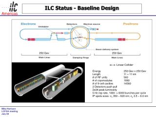
Luminosity Parameters • nominal 500 GeV luminosity: 2×1034 cm-2s-1 • We want to design to a parameter ‘space’ • Keep a range of options open • Flexibility • Risk mitigation • Current sets represent trade-offs between sub-systems • Particularly Damping Ring Beam Delivery Nick Walker - 2nd ILC Workshop - Snowmass - Colorado
50% IP vertical emittance 20nm (100%) emittance dilution budget from damping ring [TDR allowed 50%] Nominal Nick Walker - 2nd ILC Workshop - Snowmass - Colorado
Low Bunch Charge Nick Walker - 2nd ILC Workshop - Snowmass - Colorado
sy= 8nm large IP vertical emittance Nick Walker - 2nd ILC Workshop - Snowmass - Colorado
Low Average Power reduced bunch number compensation Nick Walker - 2nd ILC Workshop - Snowmass - Colorado
Low Average Power reduced bunch number compensation Nick Walker - 2nd ILC Workshop - Snowmass - Colorado
Pushing the Envelopes Nick Walker - 2nd ILC Workshop - Snowmass - Colorado
Example of Discussions Workshop allowed open discussion of new ideas and proposals Nick Walker - 2nd ILC Workshop - Snowmass - Colorado
Gradient • Baseline recommendation for cavity is standard TESLA 9-cell • Alternatives (energy upgrade): • Low-loss, • Re-entrant • superstructure Nick Walker - 2nd ILC Workshop - Snowmass - Colorado
Gradient Gradient recommendation (WG5) • 8km @ 31.5 MV/m → 250 GeV • +7km @ 36 MV/m → 500 GeV Tunnel length for one 500 GeV linac (8+7)/0.7 21km Nick Walker - 2nd ILC Workshop - Snowmass - Colorado
Gradient (WG5 Justification) Nick Walker - 2nd ILC Workshop - Snowmass - Colorado
Gradient (WG5 Justification) Nick Walker - 2nd ILC Workshop - Snowmass - Colorado
TESLA EP status Results from KEK-DESY collaboration must reduce spread (need more statistics) single-cell measurements (in nine-cell cavities) Nick Walker - 2nd ILC Workshop - Snowmass - Colorado
Cavity Fabrication Nick Walker - 2nd ILC Workshop - Snowmass - Colorado
Alternative Fabrication techniques Nick Walker - 2nd ILC Workshop - Snowmass - Colorado
Improved Processing(Electropolishing) Nick Walker - 2nd ILC Workshop - Snowmass - Colorado
Improved Cavity Shapes Nick Walker - 2nd ILC Workshop - Snowmass - Colorado
Cavity R&D Fabrication from large grain Nb discs May remove the need for electropolishing ( cost!) Nick Walker - 2nd ILC Workshop - Snowmass - Colorado
Conventional Facilities and Siting Milestone One: Snowmass 2005 Conference Successfully Initiate the Global Civil and Siting Effort Complete Comparative Site Assessment Matrix Format Milestone Two: December, 2005 Identify Regional Sample Sites for Inclusion into the Baseline Configuration Document Milestone Three: December, 2006 Complete Conventional Facilities and Siting Portion of the Reference Design Document Nick Walker - 2nd ILC Workshop - Snowmass - Colorado 8.19.05 V. Kuchler 2 of 8
Sample Site Study Nick Walker - 2nd ILC Workshop - Snowmass - Colorado
Conventional Facilities and Siting Outstanding Issues with Direct Impact on CFS Progress that will Require Further Discussion and Resolution with Other Working Groups 1 Tunnel vs 2 Tunnel Laser Straight vs Curved or Segmented Shape and Length of Damping Rings Shape and Configuration of Sources 1 vs 2 Interaction Regions Nick Walker - 2nd ILC Workshop - Snowmass - Colorado 8.19.05 V. Kuchler 6 of 8
The design is intimately tied to the features of the site 1 tunnels or 2 tunnels? Deep or shallow? Laser straight linac or follow earth’s curvature in segments? GDE ILC Design will be done to samples sites in the three regions North American sample site will be near Fermilab Japan and Europe are to determine sample sites by the end of 2005 Conventional Facilities and Siting Nick Walker - 2nd ILC Workshop - Snowmass - Colorado
Tunnel must contain Linac Cryomodule RF system Damping Ring Lines Save maybe $0.5B Issues Maintenance Safety Duty Cycle Availability/Commissioning(studies currently favour 2) 1 or 2 Linac Tunnels example Nick Walker - 2nd ILC Workshop - Snowmass - Colorado
Possible Tunnel Configurations • One tunnel or two, with variants? Nick Walker - 2nd ILC Workshop - Snowmass - Colorado
ILC Civil Program Civil engineers from all three regions working to develop methods of analyzing the siting issues and comparing sites. The current effort is not intended to select a potential site, but rather to understand from the beginning how the features of sites will effect the design, performance and cost Nick Walker - 2nd ILC Workshop - Snowmass - Colorado
Baseline Klystrons 10MW MBK 1.5ms pulse 65% efficiency Thales CPI Toshiba Nick Walker - 2nd ILC Workshop - Snowmass - Colorado
Improved Klystrons (?) 5 MW InductiveOutput Tube (IOT) 10 MW Sheet Beam Klystron (SBK) Low Voltage 10 MW MBK Voltage e.g. 65 kV Current 238A More beams Perhaps use a Direct Switch Modulator Parameters similar to 10 MW MBK Klystron Output IOT SLAC Drive CPI KEK Nick Walker - 2nd ILC Workshop - Snowmass - Colorado
RF Distribution Klystron power Cavities (12) TESLA TDR and XFEL solution (TTF) Uses many circulators to protect klystron from reflected power (and isolate couplers) Nick Walker - 2nd ILC Workshop - Snowmass - Colorado
RF Distribution Klystron power Possible improvement • Expensive circulators eliminated • Fewer types of hybrid couplers • Proper phasing causes reflections from pairs of cavities to be directed to loads • Small increase risk to klystron Two leveldivision Cavities (12) Nick Walker - 2nd ILC Workshop - Snowmass - Colorado
Modulators (115 kV, 135 A, 1.5 ms, 5 Hz) (~ 2m Long) Operation: an array of capacitors is charged in parallel, discharged in series.Will test full prototype in 2006 Pulse Transformer Style Nick Walker - 2nd ILC Workshop - Snowmass - Colorado
Damping Rings: Three variants 6km 3km 17 km ‘dogbone’ Nick Walker - 2nd ILC Workshop - Snowmass - Colorado
Damping Rings higher Iav smaller circumference (faster kicker) bunch train compression 300km 20km Nick Walker - 2nd ILC Workshop - Snowmass - Colorado
Damping Rings: Recommendation • Not Yet! • Systematic analysis of all rings being made • Dynamic aperture • Emittance performance (tolerances) • Electron cloud • Fast ion instability • … • Positive R&D on fast kickers will allow smaller circumference than TESLA dogbone • Recommendation to be made before the BCD Nick Walker - 2nd ILC Workshop - Snowmass - Colorado