Download
1 / 10
120 likes | 409 Views
Self-Induction Transducers. Coil is activated by the supply and the current produces a magnetic flux which is linked with the coil The level of flux linkage (self-inductance) can be varied by moving a ferromagnetic object within the magnetic field. AC Supply v ref. Inductance Measuring

E N D
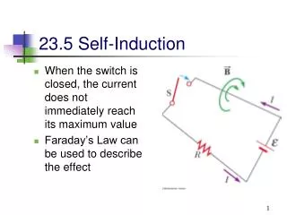
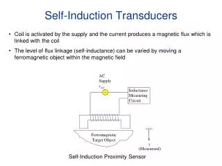
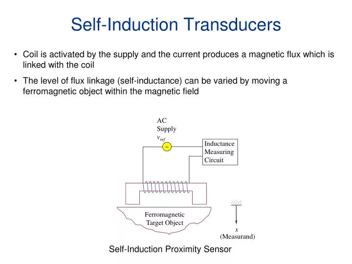
Self-Induction Transducers • Coil is activated by the supply and the current produces a magnetic flux which is linked with the coil • The level of flux linkage (self-inductance) can be varied by moving a ferromagnetic object within the magnetic field AC Supply vref Inductance Measuring Circuit ~ Ferromagnetic Target Object x (Measurand) Self-Induction Proximity Sensor
Permanent Magnet Transducers • A permanent magnet transducer uses a permanent magnet to generate the magnetic field • A relative motion between the magnetic field and an electrical conductor induces a voltage • This voltage is proportional to the speed at which the conductor crosses the magnetic field • Depending on the configuration either rectilinear speeds or angular speeds can be measured Rectilinear Permanent Magnet Output vo (Measurement) Moving Coil Velocity v (Measurand)
DC Tachometer (Angular Velocity) Speed Permanent Magnet Commutator - S N h + Rotating Coil Rotating Coil 2r vo • The rotor is directly connected to the rotating object. • The output signal that is induced at the rotating coil is picked up using a commutator device (consists of low resistance carbon brushes) • Commutator is stationary but makes contact with the split slip rings • Generated voltage is (Faraday’s Law)
Example 3.5 A dc tachometer is shown below. The field windings are powered by dc voltage vf. Angular speed ω and torque Ti are the input variables. The output voltage vo of the armature circuit and the corresponding current io are the output variables. Obtain a transfer-function model for this device. Discuss the assumptions needed to “decouple” this result into a practical input-output model for a tachometer. What are the corresponding design implications? In particular discuss the significance of the mechanical time constant and the electrical time constant of the tachometer. R i i R L f f o a a + + T g + Inertia (Output Port) J J, b L v v v f w g T o f i Damping b - - - w T i (Input Port)
Permanent Magnet AC Tachometer • When the rotor is stationary or moving in a quasi-static manner the output voltage will be constant • As the rotor moves, an additional voltage, proportional to the speed of the rotor will be induced • The output is an amplitude modulated signal proportional to the rotor speed and demodulation is necessary • Direction is obtained from the phase angle AC Carrier Source vref ~ Output vo Permanent-Magnet Rotor Secondary Stator Primary Stator • For low frequency applications (~5Hz), supply with 60Hz is adequate • Sensitivity is in the range 50 – 100mV/rad/s
AC Induction Tachometer • Similar in construction to an induction motor. Rotor windings are shorted. • The induced voltage in the rotor windings is a modulated signal of the supply. Modulation is due to the speed of the rotor. • The output voltage on the secondary is a result of primary and rotor windings and is supply modulated by the speed AC Carrier Source vref ~ Output vo Shorted Rotor Coil Secondary Stator Primary Stator • Main advantage of AC tachometers is that they have no slip rings or brushes
Eddy Current Transducers • Conducting materials when subjected to a fluctuating magnetic field produce Eddy currents • When a target object is moved closer to the sensor the inductance of the active coil changes • The two coils on the probe head form two arms of an inductance bridge • The output of the bridge is amplitude modulated signal (Measurand) x Compensating Coil Coaxial Cable Output vo • Impedance Bridge • Demodulator • Low-Pass Filter Target Object Calibrating Unit Conducting Surface RF Signal (100 MHz) Active Coil Radio Freq. Converter (Oscillator) 20 V DC Supply
Impedance Bridge Bridge Output (to Demodulator) C R2 R1 Compensating Coil RF Generator L ~ L + ΔL Active Coil R1 R2 C • The bridge is balanced when there is no object • The change in inductance creates an imbalance in the circuit and results in the output signal • The modulated signal needs to be demodulated to determine the displacement • For large displacements output is not linearly related to the displacement
Typical diameter of the probe is about 2mm (large 75mm) • The target object has to be slightly larger than the frontal area of the probe • Output impedance is about 1 kΩ (medium impedance) • Sensitivity is around 5V/mm • Range .25mm – 30mm • Suitable for high transient (100 kHz) measurements • Applications include • Displacement • Fault detection • Metal detection • Braking