Download
1 / 52
1k likes | 3.04k Views
Pressure Transducers. پروژه درس سیستم های اندازه گیری. Introduction to Pressure Transducers. What is a pressure transducer?.

E N D
Pressure Transducers پروژه درس سیستم های اندازه گیری
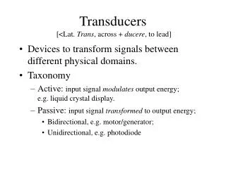
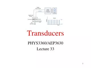
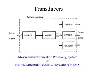
What is a pressure transducer? A pressure transducer is a transducer that converts pressure into an analog electrical signal. Although there are various types of pressure transducers, one of the most common is the strain-gage base transducer. The conversion of pressure into an electrical signal is achieved by the physical deformation of strain gages which are bonded into the diaphragm of the pressure transducer and wired into a wheatstone bridge configuration. Pressure applied to the pressure transducer produces a deflection of the diaphragm which introduces strain to the gages. The strain will produce an electrical resistance change proportional to the pressure.
Starting at the pipe threaded end, the opening or port has a stainless steel diaphragm inside that protects the sensor element from the media being measured (i.e. water).
What is inside? • As we continue our journey through the transducer we come to the other side of the diaphragm where one side of the sensor element is. The actual element is a strain gauge; that is, a resistive element whose resistance changes with the amount of strain placed on it. This variable resistor forms one leg of a bridge circuit. The other side of the strain element is the reference port that the measuring port is compared to. All transducers have two sides; sometimes the other side has its own pressure connection and the device is called a differential pressure transducer.
The insides of a modern pressure transducer Further on in our voyage, we come to small circuit board. The two voltage out points from the bridge circuit are fed to an amplifier that changes the very small voltage into a 0-5V signal or most commonly to a 4-20 mA signal. This signal is fed out the cable (sometimes along with a vent tube) which finishes our voyage. The output of a Strain gauge is sometimes referred to as ratiometric to the supply voltage. The term ratiometric means that the output varies as a ratio of the the supply voltage. An example helps make all things things clear
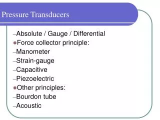
Mechanical methods of measuring pressure have been known for centuries. U-tube manometers were among the first pressure indicators. Originally, these tubes were made of glass, and scales were added to them as needed. But manometers are large, cumbersome, and not well suited for integration into automatic control loops. Therefore, manometers are usually found in the laboratory or used as local indicators. Depending on the reference pressure used, they could indicate absolute, gauge, and differential pressure.
Differential pressure transducers often are used in flow measurement where they can measure the pressure differential across a venturi, orifice, or other type of primary element. The detected pressure differential is related to flowing velocity and therefore to volumetric flow. Many features of modern pressure transmitters have come from the differential pressure transducer. In fact, one might consider the differential pressure transmitter the model for all pressure transducers.
"Gauge" pressure is defined relative to atmospheric conditions. In those parts of the world that continue to use English units, gauge pressure is indicated by adding a "g" to the units descriptor. Therefore, the pressure unit "pounds per square inch gauge" is abbreviated psig. When using SI units, it is proper to add "gauge" to the units used, such as "Pa gauge." When pressure is to be measured in absolute units, the reference is full vacuum and the abbreviation for "pounds per square inch absolute" is psia.
Often, the terms pressure gauge, sensor, transducer, and transmitter are used interchangeably. The term pressure gauge usually refers to a self-contained indicator that converts the detected process pressure into the mechanical motion of a pointer. A pressure transducer might combine the sensor element of a gauge with a mechanical-to-electrical or mechanical-to-pneumatic converter and a power supply. A pressure transmitter is a standardized pressure measurement package consisting of three basic components: a pressure transducer, its power supply, and a signal conditioner/retransmitter that converts the transducer signal into a standardized output.
Pressure transmitters can send the process pressure of interest using an analog pneumatic (3-15 psig), analog electronic (4-20 mA dc), or digital electronic signal. When transducers are directly interfaced with digital data acquisition systems and are located at some distance from the data acquisition hardware, high output voltage signals are preferred. These signals must be protected against both electromagnetic and radio frequency interference (EMI/RFI) when traveling longer distances
Pressure transducer performance-related terms also require definition. Transducer accuracy refers to the degree of conformity of the measured value to an accepted standard. It is usually expressed as a percentage of either the full scale or of the actual reading of the instrument. In case of percent-full-scale devices, error increases as the absolute value of the measurement drops. Repeatability refers to the closeness of agreement among a number of consecutive measurements of the same variable. Linearity is a measure of how well the transducer output increases linearly with increasing pressure. Hysteresis error describes the phenomenon whereby the same process pressure results in different output signals depending upon whether the pressure is approached from a lower or higher pressure.
From Mechanical to Electronic The first pressure gauges used flexible elements as sensors. As pressure changed, the flexible element moved, and this motion was used to rotate a pointer in front of a dial. In these mechanical pressure sensors, a Bourdon tube, a diaphragm, or a bellows element detected the process pressure and caused a corresponding movement.
A Bourdon tube is C-shaped and has an oval cross-section with one end of the tube connected to the process pressure (Figure 3-1A). The other end is sealed and connected to the pointer or transmitter mechanism. To increase their sensitivity, Bourdon tube elements can be extended into spirals or helical coils (Figures 3-1B and 3-1C). This increases their effective angular length and therefore increases the movement at their tip, which in turn increases the resolution of the transducer.
The family of flexible pressure sensor elements also includes the bellows and the diaphragms (Figure 3-2). Diaphragms are popular because they require less space and because the motion (or force) they produce is sufficient for operating electronic transducers. They also are available in a wide range of materials for corrosive service applications.
Many pneumatic pressure transmitters are still in operation, particularly in the petrochemical industry. But as control systems continue to become more centralized and computerized, these devices have been replaced by analog electronic and, more recently, digital electronic transmitters.
Transducer Types Figure 3-3 provides an overall orientation to the scientist or engineer who might be faced with the task of selecting a pressure detector from among the many designs available. This table shows the ranges of pressures and vacuums that various sensor types are capable of detecting and the types of internal references (vacuum or atmospheric pressure) used, if any. Because electronic pressure transducers are of greatest utility for industrial and laboratory data acquisition and control applications, the operating principles and pros and cons of each of these is further elaborated in this section
Strain Gage When a strain gage, as described in detail in Chapter 2, is used to measure the deflection of an elastic diaphragm or Bourdon tube, it becomes a component in a pressure transducer. Strain gage-type pressure transducers are widely used. Strain-gage transducers are used for narrow-span pressure and for differential pressure measurements. Essentially, the strain gage is used to measure the displacement of an elastic diaphragm due to a difference in pressure across the diaphragm. These devices can detect gauge pressure if the low pressure port is left open to the atmosphere or differential pressure if connected to two process pressures. If the low pressure side is a sealed vacuum reference, the transmitter will act as an absolute pressure transmitter.
Differential pressure tranducers in a variety of ranges and outputs
Strain gage transducers are available for pressure ranges as low as 3 inches of water to as high as 200,000 psig (1400 MPa). Inaccuracy ranges from 0.1% of span to 0.25% of full scale. Additional error sources can be a 0.25% of full scale drift over six months and a 0.25% full scale temperature effect per 1000¡ F.
Capacitance Capacitance pressure transducers were originally developed for use in low vacuum research. This capacitance change results from the movement of a diaphragm element (Figure 3-5). The diaphragm is usually metal or metal-coated quartz and is exposed to the process pressure on one side and to the reference pressure on the other. Depending on the type of pressure, the capacitive transducer can be either an absolute, gauge, or differential pressure transducer.
Stainless steel is the most common diaphragm material used, but for corrosive service, high-nickel steel alloys, such as Inconel or Hastelloy, give better performance. Tantalum also is used for highly corrosive, high temperature applications. As a special case, silver diaphragms can be used to measure the pressure of chlorine, fluorine, and other halogens in their elemental state. In a capacitance-type pressure sensor, a high-frequency, high-voltage oscillator is used to charge the sensing electrode elements. In a two-plate capacitor sensor design, the movement of the diaphragm between the plates is detected as an indication of the changes in process pressure.
As shown in Figure 3-5, the deflection of the diaphragm causes a change in capacitance that is detected by a bridge circuit. This circuit can be operated in either a balanced or unbalanced mode. In balanced mode, the output voltage is fed to a null detector and the capacitor arms are varied to maintain the bridge at null. Therefore, in the balanced mode, the null setting itself is a measure of process pressure. When operated in unbalanced mode, the process pressure measurement is related to the ratio between the output voltage and the excitation voltage
Single-plate capacitor designs are also common. In this design, the plate is located on the back side of the diaphragm and the variable capacitance is a function of deflection of the diaphragm. Therefore, the detected capacitance is an indication of the process pressure. The capacitance is converted into either a direct current or a voltage signal that can be read directly by panel meters or microprocessor-based input/output boards
Capacitance pressure transducers are widespread in part because of their wide rangeability, from high vacuums in the micron range to 10,000 psig (70 MPa). Differential pressures as low as 0.01 inches of water can readily be measured. And, compared with strain gage transducers, they do not drift much. Better designs are available that are accurate to within 0.1% of reading or 0.01% of full scale. A typical temperature effect is 0.25% of full scale per 1000¡ F.
Capacitance-type sensors are often used as secondary standards, especially in low-differential and low-absolute pressure applications. They also are quite responsive, because the distance the diaphragm must physically travel is only a few microns. Newer capacitance pressure transducers are more resistant to corrosion and are less sensitive to stray capacitance and vibration effects that used to cause "reading jitters" in older designs.
Potentiometric The potentiometric pressure sensor provides a simple method for obtaining an electronic output from a mechanical pressure gauge. The device consists of a precision potentiometer, whose wiper arm is mechanically linked to a Bourdon or bellows element. The movement of the wiper arm across the potentiometer converts the mechanically detected sensor deflection into a resistance measurement, using a Wheatstone bridge circuit (Figure 3-6).
The mechanical nature of the linkages connecting the wiper arm to the Bourdon tube, bellows, or diaphragm element introduces unavoidable errors into this type of measurement. Temperature effects cause additional errors because of the differences in thermal expansion coefficients of the metallic components of the system. Errors also will develop due to mechanical wear of the components and of the contacts
Potentiometric transducers can be made extremely small and installed in very tight quarters, such as inside the housing of a 4.5-in. dial pressure gauge. They also provide a strong output that can be read without additional amplification. This permits them to be used in low power applications. They are also inexpensive. Potentiometric transducers can detect pressures between 5 and 10,000 psig (35 KPa to 70 MPa). Their accuracy is between 0.5% and 1% of full scale, not including drift and the effects of temperature.
Resonant Wire The resonant-wire pressure transducer was introduced in the late 1970s. In this design (Figure 3-7), a wire is gripped by a static member at one end, and by the sensing diaphragm at the other. An oscillator circuit causes the wire to oscillate at its resonant frequency. A change in process pressure changes the wire tension, which in turn changes the resonant frequency of the wire. A digital counter circuit detects the shift. Because this change in frequency can be detected quite precisely, this type of transducer can be used for low differential pressure applications as well as to detect absolute and gauge pressures.
The most significant advantage of the resonant wire pressure transducer is that it generates an inherently digital signal, and therefore can be sent directly to a stable crystal clock in a microprocessor. Limitations include sensitivity to temperature variation, a nonlinear output signal, and some sensitivity to shock and vibration. These limitations typically are minimized by using a microprocessor to compensate for nonlinearities as well as ambient and process temperature variations.
Resonant wire transducers can detect absolute pressures from 10 mm Hg, differential pressures up to 750 in. water, and gauge pressures up to 6,000 psig (42 MPa). Typical accuracy is 0.1% of calibrated span, with six-month drift of 0.1% and a temperature effect of 0.2% per 1000¡ F.
Pressure transducers are generally available with three types of electrical output; millivolt, volt and 4-20mA. Below is a summary of the outputs and when they are best used. The Electrical Output of Pressure Transducers
Millivolt Output Pressure Transducers Transducers with millivolt output are normally the most economical pressure transducers. The output of the millivolt transducer is nominally around 30mV. The actual output is directly proportional to the pressure transducer input power or excitation. If the excitation fluctuates, the output will change also. Because of this dependence on the excitation level, regulated power supplies are suggested for use with millivolt transducers. Because the output signal is so low, the transducer should not be located in an electrically noisy environment. The distances between the transducer and the readout instrument should also be kept relatively short.
Voltage Output Pressure Transducers Voltage output transducers include integral signal conditioning which provide a much higher output than a millivolt transducer. The output is normally 0-5Vdc or 0-10Vdc. Although model specific, the output of the transducer is not normally a direct function of excitation. This means unregulated power supplies are often sufficient as long as they fall within a specified power range. Because they have a higher level output these transducers are not as susceptible to electrical noise as millivolt transducers and can therefore be used in much more industrial environments.
4-20 mA Output Pressure Transducers These types of transducers are also known as pressure transmitters. Since a 4-20mA signal is least affected by electrical noise and resistance in the signal wires, these transducers are best used when the signal must be transmitted long distances. It is not uncommon to use these transducers in applications where the lead wire must be 1000 feet or more
Styles of Pressure Transducers
PC Board Mountable Pressure Transducers PC board mountable pressure transducers are generally compact economical pressure transducers designed to mount on an electrical PC board and be integrated into other products.
General Purpose Transducers General purpose pressure transducers are the most common since they are designed to fit the broadest set of applications.
Heavy Duty/Industrial Pressure Transducers Heavy Duty/Industrial Pressure transducers feature a much more rugged enclosure than other transducers. They are designed to accommodate heavy industrial environments. They also often feature a scalable 4-20mA output that provides much greater immunity to electrical noise which is not uncommon in industrial environments.
High Stability/High Accuracy Pressure Transducers Most pressure transducers feature an accuracy of 0.25% of full scale or higher. High stability and high accuracy pressure transducers can offer errors as low as 0.05% of full scale, depending on model. Although more expensive than general purpose transducers, they may be the only option if high precision is required.
Flush Diaphragm Pressure Transducers With flush diaphragm pressure transducers, the diaphragm is flush to the process. This eliminates a cavity above the diaphragm that could collect fluid matter from the process. In certain applications, this may be very undesirable. Those applications include monitoring the pressure of foods or liquids that have very high viscosity