Download

1 / 70
860 likes | 1.01k Views
TRANSDUCERS. Pressure. Voltage. INTRODUCTION OF TRANSDUCERS. A transducer is a device that convert one form of energy to other form. It converts the measurand to a usable electrical signal.

E N D
Pressure Voltage INTRODUCTION OF TRANSDUCERS • A transducer is a device that convert one form of energy to other form. It converts the measurand to a usable electrical signal. • In other word it is a device that is capable of converting the physical quantity into a proportional electrical quantity such as voltage or current.
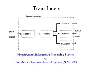
BLOCK DIAGRAM OF TRANSDUCERS • Transducer contains two parts that are closely related to each other i.e. the sensing element and transduction element. • The sensing element is called as the sensor. It is device producing measurable response to change in physical conditions. • The transduction element convert the sensor output to suitable electrical form.
CHARACTERISTICS OF TRANSDUCERS(Basic requirements of transducers) Ruggedness Linearity Repeatability Accuracy High stability and reliability Dynamic range Physical size (Small) Speed of response Sensitivity
TRANSDUCERS SELECTION FACTORS Operating Principle: The transducer are many times selected on the basis of operating principle used by them. The operating principle used may be resistive, inductive, capacitive , optoelectronic, piezo electric etc. Sensitivity: The transducer must be sensitive enough to produce detectable output. Operating Range: The transducer should maintain the range requirement and have a good resolution over the entire range. Accuracy: High accuracy is assured. Cross sensitivity: It has to be taken into account when measuring mechanical quantities. There are situation where the actual quantity is being measured is in one plane and the transducer is subjected to variation in another plan. Errors: The transducer should maintain the expected input-output relationship as described by the transfer function so as to avoid errors.
Contd. • Transient and frequency response : The transducer should meet the desired time domain specification like peak overshoot, rise time, setting time and small dynamic error. • Loading Effects: The transducer should have a high input impedance and low output impedance to avoid loading effects. • Environmental Compatibility: It should be assured that the transducer selected to work under specified environmental conditions maintains its input- output relationship and does not break down. • Insensitivity to unwanted signals: The transducer should be minimally sensitive to unwanted signals and highly sensitive to desired signals.
CLASSIFICATION OF TRANSDUCERS The transducers can be classified as: • Active and passive transducers. • Analog and digital transducers. • On the basis of transduction principle used. • Primary and secondary transducer • Transducers and inverse transducers.
ACTIVE AND PASSIVE TRANSDUCERS • Active transducers : • These transducers do not need any external source of power for their operation. Therefore they are also called as self generating type transducers. • The active transducer are self generating devices which operate under the energy conversion principle. • As the output of active transducers we get an equivalent electrical output signal e.g. temperature or strain to electric potential, without any external source of energy being used.
ACTIVE AND PASSIVE TRANSDUCERS • Passive Transducers : • These transducers need external source of power for their operation. So they are not self generating type transducers. • A DC power supply or an audio frequency generator is used as an external power source. • These transducers produce the output signal in the form of variation in resistance, capacitance, inductance or some other electrical parameter in response to the quantity to be measured.
PRIMARY AND SECONDARY TRANSDUCERS • Some transducers contain the mechanical as well as electrical device. The mechanical device converts the physical quantity to be measured into a mechanical signal. Such mechanical device are called as the primary transducers, because they deal with the physical quantity to be measured. • The electrical device then convert this mechanical signal into a corresponding electrical signal. Such electrical device are known as secondary transducers.
CONTD • Ref fig in which the diaphragm act as primary transducer. It convert pressure (the quantity to be measured) into displacement(the mechanical signal). • The displacement is then converted into change in resistance using strain gauge. Hence strain gauge acts as the secondary transducer.
CLASSIFICATION OF TRANSDUCERSAccording to Transduction Principle
d Area=A CLASSIFICATION OF TRANSDUCERSAccording to Transduction Principle • CAPACITIVE TRANSDUCER: • In capacitive transduction transducers the measurand is converted to a change in the capacitance. • • A typical capacitor is comprised of two parallel plates of conducting material separated by an electrical insulating material called a dielectric. The plates and the dielectric may be either flattened or rolled. • • The purpose of the dielectric is to help the two parallel plates maintain their stored electrical charges. • • The relationship between the capacitance and the size of capacitor plate, amount of plate separation, and the dielectric is given by • C = ε0 εr A / d • d is the separation distance of plates (m) • C is the capacitance (F, Farad) • ε0 : absolute permittivity of vacuum • εr : relative permittivity • A is the effective (overlapping) area of capacitor plates (m2) Either A, d or ε can be varied.
CLASSIFICATION OF TRANSDUCERSAccording to Transduction Principle • ELECTROMAGNETIC TRANSDUCTION: • In electromagnetic transduction, the measurand is converted to voltage induced in conductor by change in the magnetic flux, in absence of excitation. • The electromagnetic transducer are self generating active transducers • The motion between a piece of magnet and an electromagnet is responsible for the change in flux
CLASSIFICATION OF TRANSDUCERSAccording to Transduction Principle • INDUCTIVE TRANSDUCER: • In inductive transduction, the measurand is converted into a change in the self inductance of a single coil. It is achieved by displacing the core of the coil that is attached to a mechanical sensing element
CLASSIFICATION OF TRANSDUCERSAccording to Transduction Principle • PIEZO ELECTRIC INDUCTION : • In piezoelectric induction the measurand is converted into a change in electrostatic charge q or voltage V generated by crystals when mechanically it is stressed as shown in fig.
CLASSIFICATION OF TRANSDUCERSAccording to Transduction Principle • PHOTOVOLTAIC TRANSDUCTION : • In photovoltaic transduction the measurand is converted to voltage generated when the junction between dissimilar material is illuminated as shown in fig.
Physics of Photovoltaic Generation n-type semiconductor + + + + + + + + + + + + + + + Depletion Zone - - - - - - - - - - - - - - - - - - p-type semiconductor
CLASSIFICATION OF TRANSDUCERSAccording to Transduction Principle • PHOTO CONDUCTIVE TRANSDUCTION : • In photoconductive transduction the measurand is converted to change in resistance of semiconductor material by the change in light incident on the material.
CLASSIFICATION OF TRANSDUCERSTransducer and Inverse Transducer • TRANSDUCER: • Transducers convert non electrical quantity to electrical quantity. • INVERSE TRANSDUCER: • Inverse transducers convert electrical quantity to a non electrical quantity
PASSIVE TRANSDUCERS • Resistive transducers : • Resistive transducers are those transducers in which the resistance change due to the change in some physical phenomenon. • The resistance of a metal conductor is expressed by a simple equation. • R = ρL/A • Where R = resistance of conductor in Ω L = length of conductor in m A = cross sectional area of conductor in m2 ρ = resistivity of conductor material in Ω-m.
RESISTIVE TRANSDUCER There are 4 type of resistive transducers. • Potentiometers (POT) • Strain gauge • Thermistors • Resistance thermometer
POTENTIOMETER • The potentiometer are used for voltage division. They consist of a resistive element provided with a sliding contact. The sliding contact is called as wiper. • The contact motion may be linear or rotational or combination of the two. The combinational potentiometer have their resistive element in helix form and are called helipots. • Fig shows a linear pot and a rotary pot.
STRAIN GAUGE • The strain gauge is a passive, resistive transducer which converts the mechanical elongation and compression into a resistance change. • This change in resistance takes place due to variation in length and cross sectional area of the gauge wire, when an external force acts on it.
TYPES OF STRAIN GAUGE • The type of strain gauge are as • Wire gauge • Unbonded • Bonded • Foil type • Semiconductor gauge
UNBONDED STRAIN GAUGE • An unbonded meter strain gauge is shown in fig • This gauge consist of a wire stretched between two point in an insulating medium such as air. The wires may be made of various copper, nickel, crome nickle or nickle iron alloys. • In fig the element is connected via a rod to diaphragm which is used for sensing the pressure. The wire are tensioned to avoid buckling when they experience the compressive force.
The unbounded meter wire gauges used almost exclusively in transducer application employ preloaded resistance wire connected in Wheatstone bridge as shown in fig. • At initial preload the strain and resistance of the four arms are nominally equal with the result the output voltage of the bridge is equal to zero. • Application of pressure produces a small displacement , the displacement increases a tension in two wire and decreases it in the other two thereby increase the resistance of two wire which are in tension and decreasing the resistance of the remaining two wire . • This causes an unbalance of the bridge producing an output voltage which is proportional to the input displacement and hence to the applied pressure .
BONDED STRAIN GAUGE • The bonded metal wire strain gauge are used for both stress analysis and for construction of transducer. • A resistance wire strain gauge consist of a grid of fine resistance wire. The grid is cemented to carrier which may be a thin sheet of paper bakelite or teflon. • The wire is covered on top with a thin sheet of material so as to prevent it from any mechanical demage. • The carrier is bonded with an adhesive material to the specimen which permit a good transfer of strain from carrier to grid of wires.
BONDED METAL FOIL STRAIN GAUGE • It consist of following parts: • Base (carrier) Materials: several types of base material are used to support the wires. Impregnated paper is used for room temp. applications. • Adhesive: The adhesive acts as bonding materials. Like other bonding operation, successful starain gauge bonding depends upon careful surface preparation and use of the correct bonding agent. In order that the strain be faithfully transferred on to the strain gauge, the bond has to be formed between the surface to be strained and the plastic backing material on which the gauge is mounted . .
It is important that the adhesive should be suited to this backing and adhesive material should be quick drying type and also insensitive to moisture. • Leads: The leads should be of such materials which have low and stable resistivity and also a low resistance temperature coefficent
Contd. • This class of strain gauge is only an extension of the bonded metal wire strain gauges. • The bonded metal wire starin gauge have been completely superseded by bonded metal foil strain gauges. • Metal foil strain gauge use identical material to wire strain gauge and are used for most general purpose stress analysis application and for many transducers.
SEMICONDUCTOR GAUGE • Semiconductor gauge are used in application where a high gauge factor is desired. A high gauge factor means relatively higher change in resistance that can be measured with good accuracy. • The resistance of the semiconductor gauge change as strain is applied to it. The semiconductor gauge depends for their action upon the piezo-resistive effect i.e. change in value of resistance due to change in resistivity. • Silicon and germanium are used as resistive material for semiconductor gauges.
RESISTANCE THERMOMETER • Resistance of metal increase with increases in temperature. Therefore metals are said to have a positive temperature coefficient of resistivity. • Fig shows the simplest type of open wire construction of platinum résistance thermometer. The platinum wire is wound in the form of spirals on an insulating material such as mica or ceramic. • This assembly is then placed at the tip of probe • This wire is in direct contact with the gas or liquid whose temperature is to be measured.
The resistance of the platinum wire changes with the change in temperature of the gas or liquid • This type of sensor have a positive temperature coefficient of resistivity as they are made from metals they are also known as resistance temperature detector • Resistance thermometer are generally of probe type for immersion in medium whose temperature is to be measured or controlled.
THERMISTOR • Thermistor is a contraction of a term “thermal resistor”. • Thermistor are temperature dependent resistors. They are made of semiconductor material which have negative temperature coefficient of resistivity i.e. their resistance decreases with increase of temperature. • Thermistor are widely used in application which involve measurement in the range of 0-60º Thermistor are composed of sintered mixture of metallic oxides such as magnese, nickle, cobalt, copper, iron and uranium
Contd. • The thermistor may be in the form of beads, rods and discs. • The thermistor provide a large change in resistance for small change in temperature. In some cases the resistance of themistor at room temperature may decreases as much as 6% for each 1ºC rise in temperature.
Thermocouples See beck Effect When a pair of dissimilar metals are joined at one end, and there is a temperature difference between the joined ends and the open ends, thermal emf is generated, which can be measured in the open ends. This forms the basis of thermocouples.
An inductive electromechanical transducer is a transducer which converts the physical motion into the change in inductance. • Inductive transducers are mainly used for displacement measurement. VARIABLE-INDUCTANCE TRANSDUCERS