Download

1 / 16
170 likes | 1.02k Views
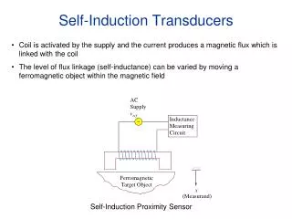
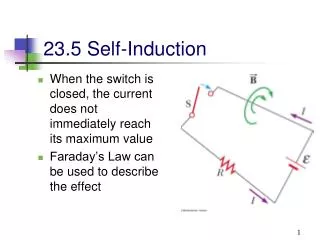
SELF INDUCTION. DURING AC FLOW, MAGNETIC FIELD IS NOT CONSTANT. AN OPPOSING ACTION WITHIN THE COIL IS PRODUCED . SELF INDUCTION. INDUCED VOLTAGE IN AC CIRCUIT WILL OPPOSE THE SOURCE VOLTAGE IF THE SOURCE OF EMF INCREASES, THE INDUCED COIL VOLTAGE WILL OPPOSE IT AND ATTEMPT TO REDUCE IT.

E N D
SELF INDUCTION DURING AC FLOW, MAGNETIC FIELD IS NOT CONSTANT. AN OPPOSING ACTION WITHIN THE COIL IS PRODUCED
SELF INDUCTION • INDUCED VOLTAGE IN AC CIRCUIT WILL OPPOSE THE SOURCE VOLTAGE • IF THE SOURCE OF EMF INCREASES, THE INDUCED COIL VOLTAGE WILL OPPOSE IT AND ATTEMPT TO REDUCE IT. • IF THE SOURCE OF EMF DECREASES, THE INDUCED COIL VOLTAGE WILL ATTEMPT TO INCREASE IT. • LINE VOLTAGE COMPENSATOR WHICH TAPS OFF OF THE AUTOTRANSFORMER IN THE X-RAY CIRCUIT
MUTUAL INDUCTION • IT IS NOT NECESSARY TO PHYSICALLY MOVE A MAGNET TO PRODUCE A CURRENT FLOW • THE INTENSITY OF THE MAGNETIC FIELD, IF IT CHANGES, WILL PRODUCE A CURRENT FLOW • HOW DOES THIS WORK?
Placing an electromagnetic near the coil and alternating the current through the electromagnet. • Therefore, mutual induction can only be generated with AC.
TRANSFORMERS • Transform potential and current energies to higher or lower intensities using electromagnetism. • Operate only on AC current • Transformers change the magnitude of current and the voltage in AC circuit • Step-up transformer • Step down transformer
TYPES OF TRANSFORMERS • CLOSED CORE • “SQUARE DOUGHNUT OF MAGNETIC MATERIAL
Autotransformer • Single iron core with only one winding • Acts as both primary and secondary • Works on self induction • Used for line voltage compensator by stepping up voltage or stepping down voltage as needed • Not suitable as a high voltage transformer
SHELL TYPE TRANSFORMER • “TRAPS” MORE MAGNETIC FIELD LINES IN PRIMARY WINDOW • MORE EFFICIENT • USED IN X-RAY EQUIPMENT
ELECTROMAGNETISM AS IT APPLYS TO X-RAY UNITS • AUTOTRANSFORMER=SELF INDUCTION (BASED ON LENZ’S LAW) • LINE VOLTAGE COMPENSATOR IS TAPPED OFF OF THE AUTOTRANSFORMER • KVP MAJOR AND MINOR ARE TAPPED OFF OF AUTOTRANSFORMER
Step up transformer: converts Voltage to Kilovoltage • Step down transformer: reduces voltage but increases current to supply to the filament (x-ray filaments need between 3-6 amps to heat up and “burn off” number of electrons for the mA station selected)
Rectifiers • Changes AC to DC • X-ray units require AC current for transformers • X-ray Tubes need DC current
RECTIFIERS • Electronic device (diodes) • Located between secondary side of step-up transformer and x-ray tube • Vacuum-tube Type • Solid State Diodes
X-ray unit • Line Voltage Compensator • Autotransformer (increases voltage 100-400) • Adjusts and reads voltage • Has a # of connections located along its length
High voltage generator • High voltage transformer • converts low voltage into kVp needed for production of x-rays • Filament transformer • Rectifiers
TRANSFORMER LOSSES OR INEFFICIENCY • Resistance : current and copper wire • hysteresis: alternating reversal of magnetic field • eddy current: (Lenz’s law) currents that oppose the changing magnetic field causes loss in efficiency (page 102-103)