Download
1 / 32
320 likes | 361 Views
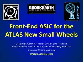
VMM - a Front-End ASIC for sTGC. Past-Present-Future ATLAS IL Dec. 2012 Technion I.I.T. VMM ASIC Family. The VMM ASIC is designed by BNL for use as a FE ASIC for MM, sTGC and others……. From this extended use, derives a series of advantages and disadvantages .

E N D
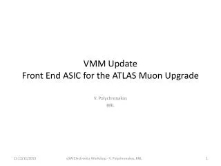
VMM - a Front-End ASIC for sTGC Past-Present-Future ATLAS IL Dec. 2012 Technion I.I.T. Lupu N. Vdovin A. Technion IIT
VMM ASIC Family • The VMM ASIC is designed by BNL for use as a FE ASIC for MM, sTGC and others……. • From this extended use, derives a series of advantages and disadvantages . • VMM1 is the first iteration of the first member of the family. • VMM1 was delivered to us around May 2012. • Since then, we have been using and learning the VMM1. Lupu N. Vdovin A. Technion IIT
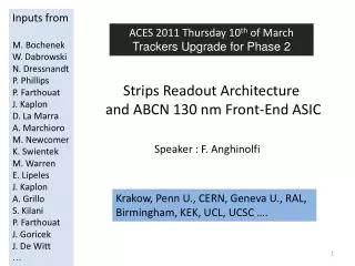
Architecture of VMM1 neighbor direct timing (ToT or TtP) logic or real time address (ART) CA shaper peak mux amplitude time mux mux timing addr mux address 64 channels logic • 200pF (few pF to nF), dual polarity, adj. gain (0.11 to 2 pC), adj. peaktime (25-200 ns), DDF • discriminator with sub-hysteresis and neighboring (channel and chip) • address of first event in real time at dedicated output (ART) • direct timing outputs (16 ch.): time-over-threshold or time-to-peak ( for TGC ) • multi-phase peak and time detector • multiplexing with sparse readout and smart token passing (channel and chip) • threshold and pulse generators, analog monitors, channel mask, temperature sensor, 600mV BGR, 600mV LVDS • power 4.5 mW/ch, size 6 x 8.4 mm², process IBM CMOS 130nm 1.2V
The Past - experience and problems • Please look atthe content of previous presentations about VMM1. • Some material is attached to the end of this presentation: • Muon New Small Wheel sTGC-VMMWish-list for VMM2 Electronics Workshop - December 2012. • Discussion between Gianluigi and Nachman, from 21-12-12 - a summary. Lupu N. Vdovin A. Technion IIT
VMM1 - sTGC • VMM1 is used in sTGC FE in 3 Modes : • STRIPS . To collect and measure the charge induced in strips for charge interpolation and calculation of centroid of event. • WIRES. Produce a logic signal used in …… • PADS. Logic output signals used in building a trigger pointer to relevant strips. In this application, the timing of the leading edge is relevant to identify the BC of the event. Lupu N. Vdovin A. Technion IIT
Performance of VMM1 with sTGC • STRIPS . In beam tests from Oct.-Nov. 2012, the VMM1 performed well . • WIRES . Only in lab. Measurements look good and beam tests should follow. • PADS. Some problems were found such astiming walk and jitter of timing, recovery from saturation . This problems were studied in the lab., and the results are presented here. Lupu N. Vdovin A. Technion IIT
Here is an illustration of the wave-forms relevant to the problem of LATENCY ,WALK and resulting JITTER of the TIMING of the Trigger pulse from sTGC pads. ToT Thr-to-Peak Lupu N. Vdovin A. Technion IIT
Monitor analog output Linear VMM1-1 Ch-2 Gain 2.24 mV/fC Threshold 250 Time over Thr Input Charge 100 fC ToT Pulse width ToT Pulse leading edge delay 37.4ns Fig 1. Time over Threshold at 100 fC input signal Fig 2. Time over Threshold at 200 fC input signal
VMM1-1 Ch-2 Gain 2.24 mV/fC Threshold 250 Monitor analog output Linear • VMM1-1 Ch-2 Gain 2.24 mV/fC Threshold 250 Time over Thr 12/29/2012 Lupu N. Vdovin A. Technion IIT Input Charge 200 fC ToT Pulse width ToT Pulse leading edge delay 31.4ns • Fig 2. Time over Threshold at 200 fC input signal Lupu N. Vdovin A. Technion IIT
VMM1-1 Ch-2 Gain 2.24 mV/fC Threshold 250 An Monitor Time over Thr Input Charge 400 fC Fig 3. Time over Threshold at 400 fc input signal ToT Pulse leading edge delay 27.85ns • Fig 3. Time over Threshold at 400 fC input signal The total walk of the leading edge of the ToT when input signal changes from a minimum to saturation is ~ 10 ns. Lupu N. Vdovin A. Technion IIT
Results of measurements performed in the lab. The timing of all the relevant signals was studied as a function of the value of the input charge and the discrimination level. VMM1-1 Ch 2 Positive Inp. Gain 2.24 mV/fC Thr = 200 Lupu N. Vdovin A. Technion IIT
VMM1-1 Ch-2 Positive Input Signal Gain 2.24 mV/fC Delay between Leading Edge of Input and Trailing Edge of Threshold-to -Peak If we consider a range of Pads’ Charges from 100 to 500 fC the Walk of the trailing edge is from -1 to +1 ns , with a latency of 62 ns. Lupu N. Vdovin A. Technion IIT
VMM1-VMM2 as a FE ASIC forPads and Trigger We need a discussion and a decision on the above point. Gianluigi speaks about a reduction to the real nominal value of the Peaking Time, which may reduce the latency by ~ 10-15 ns. Lupu N. Vdovin A. Technion IIT
Example of Wires + VMM1 • The signal is negative in this case and some features of VMM1 look better . Lupu N. Vdovin A. Technion IIT
VMM1-Ch-63 Gain 2.4 mV/fC VMM1-Ch-63 Gain 5.4 mV/fC Lupu N. Vdovin A. Technion IIT
The FUTURE • The FUTURE in this presentation’s context has three components: a. The VMM b. The Lab. Activity c. The Technion - ATLAS in NSW project. All three are to be discussed at the appropriate level and time . Lupu N. Vdovin A. Technion IIT
VMM2 • VMM2 is the second member of the VMM family of ASICs. • It is hoped to be submitted to fabrication in May 2013. • It is hoped to be produced by July-August 2013. • It is hoped to be delivered to us by September 2013. Lupu N. Vdovin A. Technion IIT
Plans for VMM2 trigger neighbor direct timing (ToT, TtP, PDAD) logic or real time address (ART) 6b PDAD timing clock mux CA shaper peak 10b ADC mux mux 10b ADC time FIFO data (ampl., time, addr.) 6b coarse mux addr. channel count logic data clock • fixes, higher gain setting, lower gain setting (5pC) • external trigger • 6-bit peak detector and digitizer (PDAD) for direct timing • 10-bit 5MS/s ADCs per channel and FIFO • fully digital IOs, derandomization, simultaneous measurement and readout • counter for coarse timing
The Lab.Elementary Particles, Physics, Technion • Electronics Instrumentation a. Develop a Data Acquisition card for VMM1 to be used in the intermediary period. (2013) b. To provide assistance with electronics systems to whoever requires it.( ATLAS IL. ) • To provide a test bench for Detector Chamber. • To participate in the Beam-Tests if required . • We made notableprogress by buying a SCOPE. Lupu N. Vdovin A. Technion IIT
Technion-ATLAS in NSW project • TBD by the relevant forum. Lupu N. Vdovin A. Technion IIT
Summary of Gianluigy presentation of VMM1- VMM2 • VMM1 has been developed and tested, with results in good agreement with the design • main issues • charge amplifier compensation • large leakage from ESD • mixed-signal parasitics • voltage drop on supply/ground wire-bonds • uniformity • Recovery from saturation • VMM2 will integrate fixes and improvements for simultaneous measurement and readout • gain ranges, external trigger, ADCs, counters • PDADs (TGC), 64 timing outputs (TGC) • in design, submission 1-2 QT 2013
Summary We had an intensive and successful year regarding the front-end electronics for sTGC . The VMM1, as the first iteration of the VMM ASIC family, proved to be satisfactory on most parameters. Problems with the T-o-T were solved by replacing it with the measurement of Peak-Value, an existing feature in VMM1. Digitization will be added in VMM2. The use of VMM for Pads and Timing looks promising, if Threshold-to-Peak trailing edge is accepted. The design of the VMM2 is on the right track. The collaboration with the BNL is good. Lupu N. Vdovin A. Technion IIT
The End • Thank you for your attention. • Thank you for the good will that you have shown in understanding such a compressed presentation. • If and when anyone should need details, more information about the FEE and VMM, please don’t hesitate to ask, off line . • I wish all of us a good collaboration on the NEW SMALL WHEEL ATLAS project and A HAPPY NEW YEAR 2013 and beyond. Lupu N. Vdovin A. Technion IIT
Backup slides Lupu N. Vdovin A. Technion IIT
VMM1-1 Ch-2 Positive Input Gain 2.24 mV/fC Lupu N. Vdovin A. Technion IIT
VMM1-1 Ch-2 Positive Input Gain 2.24 mV/fC Lupu N. Vdovin A. Technion IIT
VMM1-1 Ch-2 Positive Input Gain 2.24 mV/fC Lupu N. Vdovin A. Technion IIT
VMM1-1 Ch-2 Positive Input Gain 5.4 mV/fC Lupu N. Vdovin A. Technion IIT
VMM1-1 Ch-2 Positive Input Gain 5.4 mV/fC Lupu N. Vdovin A. Technion IIT