Download
1 / 38
380 likes | 384 Views
Status of BEPCII and CSNS Power Supply System. Qi Xin May. 23. 2012 DESY. www. ihep .ac.cn. Outline. Introduction BEPCII Power Supply System CSNS Power Supply System Prototyping R&D for CSNS PS. BEPC II.

E N D
Status of BEPCII and CSNS Power Supply System Qi Xin May. 23. 2012 DESY www.ihep.ac.cn
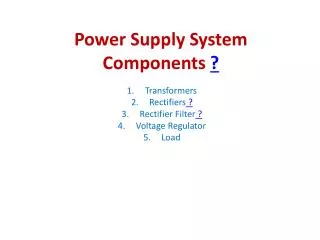
Outline • Introduction • BEPCII Power Supply System • CSNS Power Supply System • Prototyping R&D for CSNS PS
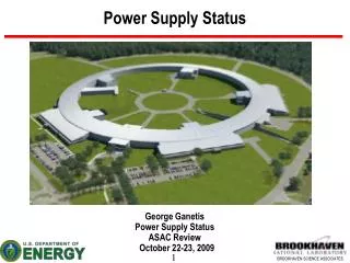
BEPC II BEPC II is a two-ring e+e- collider running in the tau-charm energy region (Ecm = 2.0-4.2 GeV), which, with a design luminosity of 1 *1033 cm-2s-1 at the beam energy of 1.89 GeV, is an improvement of a factor of 100 over its successful predecessor, BEPC. Its installation was completed in the summer of 2005 and it has reached most of the design specifications. The collider consists of two 237.5 m long storage rings, one for electrons and one for positrons. They collide at the interaction point with a horizontal crossing angle of 11 mrad and a bunch spacing of 8 ns. Each ring holds 93 bunches with a beam current of 910 mA. The machine will also provide a high flux of synchrotron radiation at a beam energy of 2.5 GeV.
General layout for BEPCII Injector Double Storage Ring Transport Line BESIII BSRF
BEPCII Power Supply System Total 650 sets, DC PS, 2 kinds: • SCR power supply 1000A/300V, 4 sets , dipole magnet PS • Switch power supply 200A/70V, chopper, 152 sets, quadrupole and sextupole magnet PS 1700A/120V, 3 sets, insertion quadruple magnet PS …… • All for analog control PS
CSNS -China Spallation Neutron Source Baseline Schedule February 2001 idea of CSNS discussed prototyping R&D January 2006 – detail design January 2011 – December 2011 construction start September 2011 civil construction December 2012 – March 2017 component fabrication September 2011 – September 2015 installation & tests June 2013 – March 2017 RCS commissioning start March 2016 first beam on target March 2017 project complete/operation start March 2018 (6.5 years from start) The site of CSNS has been selected at Dongguan, Guangdong Province
CSNS Power Supply System MEBT DC PS LRBT DC PS DTL DC PS LEBT DC PS Injection DC PS 6 sets Resonant PS Programmable Pulse PS Corrector DC PS Extraction DC PS RTBT DC PS
CSNS Power Supply System Total 303 sets, three operation modes: • DC mode from 10A to 1700A, 239 sets • AC+DC mode(frequency 25Hz) 2200A/6000V, 1set 1700A/4000V, 1set 1700A/1500V, 1set 1700A/1000V, 3sets • Programmable Pulse mode 28A/400V, 36 sets • Full digital control PS
Resonant network structure for BM &QM Serial resonant network
Power Supply Topology Diode rectifier + H type PWM inverter
Prototyping R&D for CSNS • Prototype for Dipole Power Supply(2006.10-2010.11); • Choke and capacitor bank(2007.2-2010.11); • Prototype for Quadrupole Power Supply(2009.10-2011.10); • Prototype for Trim-B Power Supply(2010.6-2011.8); • Digital Power Supply Control Module(2005- ;
Specification of the B-PS prototype • Output current: 1260A+900sint; • Output Peak Voltage : 230V; • Extraction current stability: 100ppm/8H; • Injection current stability: 500ppm/8H; • Frequency stability: 100ppm/8H; • THD: 0.02%;
Test result • Extraction current long term stability: 3.710-5/8H; • Injection current long term stability: 2.2 10-4/8H; • Frequency stability: 2 10-5/8H.
Choke and Capacitor • Choke is design with multi-gaps, oil cooling tank. The winding is used the copper strip, the core is used in steel rolling direction; • Capacitor is a single-phase power capacitor of all film type, with very low dielectric losses and long lifetime.
Specification of the Q-PS prototype • DC mode: • Output: 2000A/120V; • Long term stability: 50ppm; • AC mode: • Output current: 1150A+820sint; • Output peak voltage: 300V; • DC current stability: 100ppm/8H; • AC current stability: 100ppm/8H; • Frequency stability: 100ppm/8H; • Tracking error: 0.1%
Power Supply prototype for QM Diode rectifier +Boost+ H type PWM inverter
Test result • DC mode Currentstability: 3.9910-5/8H
Test result • AC mode, 915+652sinwt A; DC current stability: 5.05 10-5/8H; AC current stability: 8.09 10-5/8H; Frequency stability: 1.27 10-5/8H; Tracking error: 0.07%
Specification of the Trim-B PS prototype • Any programmable pulse waveform; • Output peak current: ±28 A; • Output peak voltage: 400V; • Maximum di/dt: ≥5.6A/mS; • Tracking error: 3%. parallel resonant half-bridge rectifier +H type chopper
Test result • Trapezoidal wave: removal of the inflection point; • Maximum di/dt:5.6A/mS; • Tracking error: 0.7%.
Test result • Arbitrary waveform: reference to ISIS Trim-B; • Maximum di/dt:6.5A/mS; • Tracking error: -2.5% / 2%.
Digital Power Supply Control Module(DPSCM) • Based on FPGA; • Physical connection: optical fiber; • Communication protocol: RS-232;
Problem both in B-PS and Q-PS • Magnet inductance non-linearity( test result) • BM: ≈ 14% • QM: ≈7% • Choke: ≈ 1.4% • Power supply output voltage
Digital Control for B-PS and Q-PS Change control strategy Current Tracking Magnet Field Tracking Perfect sinusoidal field High order harmonic current vector control
Digital Control for B-PS and Q-PS • In ensuring perfect sinusoidal magnetic field under the premise, the real time calculation method replacesthe look-up table method . • Through precisely controlling the current amplitude and 25Hz phase to obtain the B/Q magnet field tracking. • A 100kHz clock signal is used the synchronize the digital Power Supply Control Module (DPSCM). • A 25 Hz trigger signal is used to synchronize for BM and QM.
Digital Control for B-PS and Q-PS High order harmonic current vector control one with the original harmonic magnetic field of similar amplitude, phase contrast harmonic field is injected to reverse the original harmonic field , which makes the harmonic field small enough.
Compare with J-PARC J-PARC CSNS
Summary Control strategy • New control strategy solves the technical problem and DPSCM work well. Power supply • Not too much consideration of the magnet inductance nonlinearity . • Pay more attention to the current stability,the DC ripple and the bandwidth. • Pay more attention to high voltage insulation, energy feedback protection, grounding protection, module generalization and safety interlock protection.
Thank you! Mailing address 19B Yuquan Lu/ Shijingshan District / Beijing/ China 100049