Download
1 / 38
380 likes | 394 Views
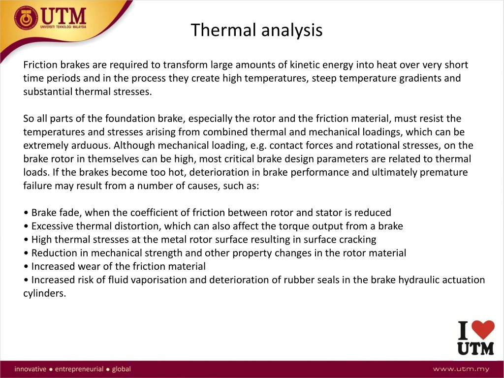
Thermal analysis. Friction brakes are required to transform large amounts of kinetic energy into heat over very short time periods and in the process they create high temperatures, steep temperature gradients and substantial thermal stresses.

E N D
Thermal analysis Friction brakes are required to transform large amounts of kinetic energy into heat over very short time periods and in the process they create high temperatures, steep temperature gradients and substantial thermal stresses. So all parts of the foundation brake, especially the rotor and the friction material, must resist the temperatures and stresses arising from combined thermal and mechanical loadings, which can be extremely arduous. Although mechanical loading, e.g. contact forces and rotational stresses, on the brake rotor in themselves can be high, most critical brake design parameters are related to thermal loads. If the brakes become too hot, deterioration in brake performance and ultimately premature failure may result from a number of causes, such as: • Brake fade, when the coefficient of friction between rotor and stator is reduced • Excessive thermal distortion, which can also affect the torque output from a brake • High thermal stresses at the metal rotor surface resulting in surface cracking • Reduction in mechanical strength and other property changes in the rotor material • Increased wear of the friction material • Increased risk of fluid vaporisation and deterioration of rubber seals in the brake hydraulic actuation cylinders.
The main factors that limit performance in single brake applications are high surface temperatures and consequent high thermal gradients that may give rise to thermal stresses sufficient to cause damage to the disc or drum. During repeated or drag braking, factors including the thermal capacity of the brake and surface heat transfer coefficients influence the peak temperatures attained, which need to be limited to avoid operational problems. Thermal analysis is an essential part of the vehicle braking system layout design process and require calculations or predictions of the following parameters: • Friction pair surface temperatures and temperature distributions • Thermal and thermo mechanical stresses • Thermal deformations and deflections • Cooling characteristics • Brake fluid temperatures • Temperatures of seals, bearings and associated brake components. Brake thermal analysis is also essential for design optimisation, material specification, brake friction performance prediction (e.g. fade at higher temperatures), component fatigue and wear life, cooling, and noise and judder (brake NVH).
For good thermal performance a brake rotor material should have high thermal conductivity (k), a high specific heat capacity (Cp) and high density (r) in order to facilitate heat flow and absorption. • The three types of braking conditions that can be defined for brake thermal performance analysis in road vehicles are: • Single application of the vehicle’s brakes; often termed ‘stops’ (to rest) or ‘snubs’ • 2. Repeated application of the vehicle’s brakes; often associated with fade tests. • 3. Continuous application of the vehicle’s brakes, often called drag braking; usually • associated with the maintenance of a constant speed on a long downhill gradient. • Thermal analysis can be carried out using: • Theoretical approach • Numerical approach: Finite element (FE) and Computational Fluid Dynamic (CFD) • Experimental approach
FE versus CFD FE analysis models the brake components and the heat dissipation from them using surface heat transfer coefficients representing all three modes of heat dissipation. The surface heat transfer coefficients for each mode must be defined and the resulting thermal or combined thermo-mechanical stresses and deflections can be calculated using the same models. CFD analysis modelsthe fluid (air) in which the brake operates and thus can predict how the convective heat dissipation varies around the brake (and the vehicle) depending on the airflow. It is possible to combine these two methods to create a very sophisticated simulation that includes conductive and radiative heat dissipation as well, but the conditions and laws of conductive and radiative heat dissipation must be defined by the user. In general, CFD analyses are much more complicated and require more time and more computingresources than FE analyses, but they do enable details of the brake installation in the vehicle and the influence of the real brake environment to be effectively modelled. To make brake thermal modelling more efficient, CFD analyses are often used to calculate convective heat transfer coefficients for typical brake design and operating conditions, which are then used in FE analyses. Experimental verification is important in all modelling and simulation to build confidence in the predictive techniques.
Theoretical approach The rotational inertia associated with the wheel and brake was broadly estimated as 5%, so the total kinetic energy could be approximated as 1.05 Qke
Braking power defines the rate of frictional energy transformation and is needed to calculate heat flux input for brake thermal analysis.
Determination of the braking energy distribution for each part of a friction pair This equation suggests that for the example disc brake about 98.4% of the braking energy would flow into the disc, while only 1.6% flows into the pads. This means that it can be assumed that 100% of the total braking energy Q = Qs can be used as the heat input to the rotor component of friction pairs (disc or drum) for the purposes of temperature prediction in these components
Example M = 2200 kg, braking distribution of 72/28, ambienty temperature of 35 Celsius, disc inner diameter of 127mm, disc outer diameter of 226 mm, disc density of 7200 kg/m^3, disc thickness of 30 mm, thermal conductivity of 45 W/mK, and specific heat of 550 J/kgK. Calculate surface temperature over time and maximum surface temperature of the front brake when a car decelerating at 0.8g from a speed of 128 km/h. Consider heat distribution onto disc 0.9 and braking ratio of 70/30.
Example Given M = 1300 kg, m = 2.2 kg, h = 70 W/m^2K, brake ratio of 65/35, initial temperature of 65 Celsius, ambient temperature of 20 Celcius, disc inner diameter of 127mm, disc outer diameter of 226 mm and specific heat of 550 J/kgK. Q1. The brake system is tested from a speed of 60 km/h at a deceleration of 3.6 m/s^2. The cycle distance is 1.61km and the cooling cycle time is 88s. Calculate the brake front temperature after 5th, 10th and 200th stop. Q2. Calculate the front brake temperature of a vehicle descending a 7% slope at a constant vehicle speed of 40 km/h for a distance of 1, 4 and 8 km.
Example. • Q1. Calculate convective heat transfer coefficient of the disc based on the following data: • Vehicle speed: 50 , 80 and 120 km/h • Outer diameter of the disc: 227 mm • Outer diameter of the wheel : 553 mm • Air elevated temperature : 20, 100 and 300 deg. C • Q2. Calculate convective heat transfer coefficient of the vane based on the following data: • Vehicle speed: 50 , 80 and 120 km/h • Outer diameter of the disc: 227 mm • Outer diameter of the wheel : 553 mm • Air elevated temperature: 20, 100 and 300 deg. C • Length of cooling vane: 60 mm • Width and height of the wetted area: 15 mm X 8 mm • Q3. Calculate heat dissipation of the disc using data from Q1, disc inner diameter of • 127 mm, ambient temperature of 20 deg. C and disc surface temperature of 300 deg. C.
Example: Compute the radiative heat transfer coefficient given that
EXPERIMENTAL APPROACH https://www.youtube.com/watch?v=VEL9diENZY0