Download
1 / 14
140 likes | 337 Views
Thermal Analysis. Lindy Ahr Southwest Research Institute (210) 522-3212 lahr@swri.org. Purpose. Spacecraft Electronics must have the highest reliability High Junction Temperatures reduce reliability Electronics Allowable Maximum Junction Temperatures are derated to increase reliability

E N D
Thermal Analysis Lindy Ahr Southwest Research Institute (210) 522-3212 lahr@swri.org
Purpose • Spacecraft Electronics must have the highest reliability • High Junction Temperatures reduce reliability • Electronics Allowable Maximum Junction Temperatures are derated to increase reliability • Thermal Analysis is used to keep the Electronic Component Temperatures below the derated temperature
Thermal Assumptions • Chassis dissipates waste heat through conduction via mounting flanges to spacecraft. • Heat transfer from each electronic module into the housing is through the card guides in the form of conduction • Individual components with 50 milliwatts, or greater power dissipation, are explicitly modeled with the remainder of the power from components being averaged across the board • Component conduction is via thermal epoxy for surface mount IC’s, solder connections for surface mount leadless devices and pins for through-hole devices that do not receive epoxy or other thermal treatment • All circuit boards have dedicated thermal planes of 4 ounces of copper in addition to power and ground planes • Power dissipation on boards is taken as nominal expected for all boards. This assumes that worst case dissipations for the entire assembly would not exceed this condition.
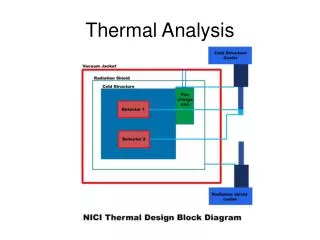
Steady-State Analysis Approach • TAK 2000 finite difference software used to model the enclosure. • Power from modules are used as heat sources at the respective nodes in the enclosure model. • Steady-state temperature profile of the housing was determined and used as boundary conditions on the card models. • Electronics modeling package in TAK 2000, PC Analyze, was used to construct card models. • Card models are comprised of parallel conductors representing the board substrate and the thermal plane, and conductors representing the edge guides. • An equivalent conductance for the board-card guide-wedge clamp-housing thermal path was determined and input into the PC Build models.
Summary • Insufficient information to accurately model the POW, DIG and ANA Card Modules. Board with uniformly distributed power were modeled. Board Temperatures were plotted. • CPU Card Module Results indicate that all analyzed device temperatures meet derating guidelines for junction temperatures for the Flight Hot Temperature Case.