Download
1 / 27
270 likes | 284 Views
CRaTER Thermal Analysis. Bob Goeke for Huade Tan. Contents. System Overview Design & Requirements Inputs and Assumptions Power Dissipations Environment and Orbit Current Model Results Instrument temperatures Orbital temperature ranges Conclusions Uncertainties and Improvements.

E N D
CRaTER Thermal Analysis Bob Goeke for Huade Tan
Contents • System Overview • Design & Requirements • Inputs and Assumptions • Power Dissipations • Environment and Orbit • Current Model • Results • Instrument temperatures • Orbital temperature ranges • Conclusions • Uncertainties and Improvements Thermal Engineering
Design Approach & Requirements • Design Approach • Radiatively isolated with multi-layer thermal blanket over entire surface. • Single layer blanket covering 10cm2 telescope apertures nadir and zenith • Tight conductive coupling to spacecraft optical bench • Interface Requirements at Instrument Mounting Surface Thermal Engineering
Model Requirements • The CRaTER thermal model is required to represent, with as much detail as possible, the behavior of critical reference points in the CRaTER instrument in a computer simulated mission orbit environment in order to anticipate and correct for any possible hardware degradation or failure under similar circumstances. • In order to ensure the survival of the CRaTER instrument, the thermal model should account for the worst case scenarios in both hot and cold temperature limits. • The model must adhere to all RGMM and RTMM requirements given in the TICD. Thermal Engineering
Instrument Power Consumption • Power dissipations in the instrument are modeled as heat loads. The relevant values of such heat loads are given in the following table. Hot case numbers are taken to be 120% of nominal and cold case numbers are assumed to be 80 % of the nominal power consumption of each electrical component. Thermal Engineering
MLI and Optical Bench • Surface finish properties: • Effective emittance: • e* for MLI assumed to be .005 or .03 for best and worst cases. • Modeled optical bench temperatures are +25 C hot case, –30 C cold case and –40 C cold survival case. Thermal Engineering
Environmental Parameters • Orbital Heat Rate Factors: • Lunar surface IR constants modeled after the characteristic Lambertian surface having a subsolar temperature of 1420 w/m2 hot case and 1280 w/ m2 cold case to a shadow IR emission of 5 w/m2 for both cases.. • Surface IR emissions across the bright side are described in the General Thermal Subsystem specification 431-SPEC-000091. Thermal Engineering
Orbit • The current instrument model is assumed to be in a basic polar orbit at a hot case altitude of 30 km. • At a Beta angle of zero, the model simulates the hot operational worst case scenario where the instrument cycles from one temperature extreme to the other. • The total heat absorbed (solar, albedo & IR) by the instrument through each orbit is computed using the Radcad Monte Carlo ray trace method. Thermal Engineering
Orbit • This latest spacecraft geometric model received from GSFS (as seen to the left) corresponds to the hot case solar array orientation. • For the Beta 0 case, the solar array articulates during the orbit. • Given the latest results of the model, minor changes in heat loads should not generate significant changes in temperature. Thermal Engineering
Orbit • The current instrument model is assumed to be in a basic polar orbit at a cold case altitude of 70 km. • At a Beta angle of 90 degrees, the model simulates the cold operational worst case scenario where the instrument never crosses the subsolar point. • The total heat absorbed (solar, albedo & IR) by the instrument through each orbit is computed using the Radcad Monte Carlo ray trace method. Thermal Engineering
Orbit • This latest spacecraft geometric model received from GSFS (as seen to the left) corresponds to the Beta 90 cold case solar array orientation. • The solar array is stationary in this case and faces the sun at all points in the orbit. • Given the latest results of the model, minor changes in heat loads should not generate significant changes in temperature. Thermal Engineering
Orbit • This latest spacecraft geometric model received from GSFS (as seen to the left) corresponds to the Beta 90 cold survival case solar array orientation. • The solar array is stationary in this case and faces the sun at all points in the orbit. • LRO is flying in a solar inertial mode with the –Y pointing at the sun at all times. • During this case, the instrument will never be in direct sunlight due to the placement of the solar array. Thermal Engineering
Current Instrument Model • The coordinate system used in the CRaTER model corresponds with the reference coordinate system of the spacecraft as outlined in the TICD. • The current instrument model consists of 60 nodes and 52 surfaces. Thermal Engineering
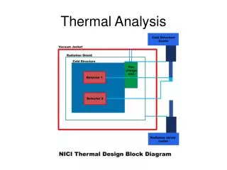
Current Instrument Schematic • The CRaTER instrument is divided into three distinct radiatively coupled regions. • Each housing consists of an isolated PCB or group of PCBs and a specific power dissipation as described in the model inputs. Analog Housing Telescope Housing Digital Housing Thermal Engineering
Mounting Footprint • CRaTER’s current design mounts to the spacecraft at six points located at the base of the electronics box. • Each modeled mounting plate is scaled to adjust for the true contact surface area. • The model assumes a contact conductance between the mounting feet and the optical bench of 1.3 W/C per mounting foot. • The surface finish of the instrument panel directly facing the LRO is assumed to be anodized aluminum with an emissivity of 0.6. Thermal Engineering
Results Summary • CRaTER is driven by the temperature of the optical bench. • Instrument Internal temperatures vary <5 C from the optical bench temperature between extremes of hot and cold. Thermal Engineering
Summary and Conclusions • Estimate of Internal Temperatures: • Maximum internal temperatures are no more than 5 degrees C above the interface temperature. • Uncertainties and Modeling Improvements: • Temperature dependence of material properties: variations in thermal conductivity can be neglected given an instrument temperature fluctuation of no more than a few degrees C through the beta 0 orbit. • Incorporating TEPs into the thermal model • Incorporating actual circuitry details on the PCBs Thermal Engineering
Electronic Component Temperatures • There are only 3 electrical components on the PC boards which draw more than 100mw of power: Part Typ. Pwr. Theta JC Rise • 1553 Interface 1100 mw 7.6 C/W 8.4 C • Actel FPGA 330 mw 2.0 C/W 0.7 C • BAE SRAM 100 mw 11 C/W 1.1 C • 2.5 Linear Regulator 170 mw 2.3 C/W 0.4 C • The 1553 part has a surface area of 4 in2; if the only heat rejection path were radiation from its top surface to the e-box walls, the junction temp would be 101C -- still below the required (derated) limit of 110C. Tests on the engineering unit will guide us in adding some more margin to this component. • The other point sources of heat are the regulated power supplies; these are mounted directly to the enclosure mid-plate with 3 #10-32 bolts each. • Both the 1553 Interface and the dual power supply are monitored in the normal housekeeping stream. Thermal Engineering
Inputs • Thermal and Physical properties: • Optical Properties: Thermal Engineering
Assumptions • Material properties: • Thermophysical properties of Al-6061 were taken from Matweb databases • Optical properties of Aluminum obtained from Cooling Techniques for Electronic Equipment: Second Edition • MLI assumptions: • Currently modeled using bulk properties • PCB assumptions: • 2 ground and power layers (80% fill) and 4 signal layers (20% fill), 1 mm total thickness • PCB properties determined at www.frigprim.com/online/cond_pcb.html • TEP assumptions: • Currently not modeled Thermal Engineering
Assumptions • Conductive Resistances: • Interface characteristics between PCB and Aluminum are assumed to be of copper to aluminum in vacuum at 30 C referred to in Heat Transfer. Holman, J.P • Surfaces of the Ebox are assumed to behave under characteristic conduction of Al-6061 (assuming that the ebox is constructed out of a single block of aluminum) • Conductive resistances are modeled between the top and bottom covers of the ebox, and the interface between the ebox and the telescope assembly. • Internal Radiation: • View factors between internal surfaces determined by Radcad using radk ray trace method • Emissivity factors are calculated assuming either infinite parallel planes or general case for two surfaces from PCBs to the interior walls. • Heat Flow to the Space Craft: • Assuming interface temperatures of –40 -30 and 25 degrees C • Contact conductance of mounting feet to LRO assumed to be 1.3 W/C per foot • Radiative heat transfer to the LRO through 15 layer MLI Thermal Engineering