Download
1 / 30
300 likes | 468 Views
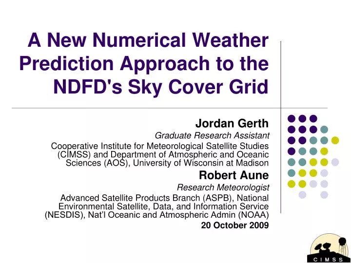
A New Numerical Weather Prediction Approach to the NDFD's Sky Cover Grid. Jordan Gerth Graduate Research Assistant Cooperative Institute for Meteorological Satellite Studies (CIMSS) and Department of Atmospheric and Oceanic Sciences (AOS), University of Wisconsin at Madison Robert Aune

E N D
A New Numerical Weather Prediction Approach to the NDFD's Sky Cover Grid Jordan Gerth Graduate Research Assistant Cooperative Institute for Meteorological Satellite Studies (CIMSS) and Department of Atmospheric and Oceanic Sciences (AOS), University of Wisconsin at Madison Robert Aune Research Meteorologist Advanced Satellite Products Branch (ASPB), National Environmental Satellite, Data, and Information Service (NESDIS), Nat’l Oceanic and Atmospheric Admin (NOAA) 20 October 2009
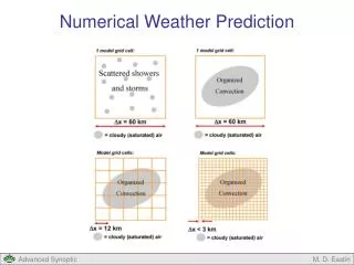
Motivation • Sky cover composites from the National Digital Forecast Database (NDFD) lack sufficient integrity from weak office-to-office consistency, and are relatively smooth definition within individual forecast areas. • Since sky conditions alone are never hazardous, and NDFD text output translates a percent into categorical terms, forecasters generally place more attention on the other forecast elements. • Existing operational numerical weather prediction models do not provide a sufficient first-guess for sky cover, relying heavily on relative humidity in the lower and middle levels of the atmosphere.
Motivation Example operational output
Definition • The NWS/NOAA web site defines “sky cover” as “the expected amount of opaque clouds (in percent) covering the sky valid for the indicated hour.” • No probabilistic component. • No definition of “opaque cloud” or “cloud”. • The implication is cloud coverage of the celestial dome (all sky visible from a point observer). • As of July 2009, the NWS Performance Branch released verification procedures which use METARs and the Effective Cloud Amount (ECA) product from satellite to form a Satellite Cloud Product (SCP).
Cloudy? Cirrostratus (Cs) covering the whole sky http://www.srh.weather.gov/srh/jetstream/synoptic/h7.htm
Experiment • The purpose of the CIMSS Regional Assimilation System is to test the use of satellite observations in numerical weather prediction model and validate outputted synthetic water vapor and infrared window imagery against actual Geostationary Operational Environmental Satellite (GOES) imagery. • Since clouds are produced on the CRAS grid using model cloud physics as an upper constraint, the CRAS is a useful tool for producing a total sky cover grid comparable to the NDFD’s sky cover sensible weather element as a prototype. • Objective: Reduce NWS forecaster preparation time for the sky cover grid, increase detail, and remove artificial boundaries, particularly through 48 hours.
Increased Local Office Detail Davenport also likes the idea of putting more detail in the sky grids... Credit: Unknown
CIMSS Regional Assimilation System (CRAS) The 12-hour spin-up currently uses: • 3-layer precipitable water (mm) from the GOES-11/12 sounders • Cloud-top pressure (hPa) and effective cloud amount (%) from the GOES-11/12 sounders • 4-layer thickness (m) from the GOES-11/12 sounders • Cloud-top pressure (hPa) from MODIS • Gridded hourly precipitation amounts from NCEP • Cloud-track and water vapor winds (m/s) from the GOES-11/12 imagers • Cloud-top pressure (hPa) and effective cloud amount (%) from the GOES-12 imagers • Surface temperature (C), dew points (C) and winds (m/s) • Sea surface temperature (C) and sea ice coverage (%) from NCEP rtg analysis
CRAS Bulk Mixed-PhaseCloud Microphysics • Explicit cloud and precipitation microphysics (Raymond, 1995), with diagnosed liquid/ice phase (Dudhia, 1989). • Precipitation fall velocity using sub-time step loop (Liu and Orville, 1969). • Water/ice cloud sedimentation (Lee, 1992). • Collision-coalescence, precipitation evaporation and auto-conversion micro-physics follows Sundquist, 1989. Relative humidity limits for cloud evaporation vary with temperature. Relative humidity for cloud condensation is less than 100% in the boundary layer. • Shallow convection scheme is turned off. The non-local turbulence scheme drives the formation of single layer cloud fields.
Methodology Outline • Compute a cloud concentration profile. • Average the profile for the upper and lower troposphere based on the number of cloud layers. • Determine the local sky cover. • Combine adjacent grid points to form an upper and lower celestial dome, then combine the two domes, giving the lower celestial dome preference.
Methodology • The first step is to compute a point-by-point, level-by-level cloud concentration. • For every grid point at each vertical level, if cloud mixing ratio is greater than or equal to 0.01 g/kg, then a ratio is computed of this mixing ratio to the auto-conversion limit (based solely on the temperature at that grid point). • The resulting ratio, generally between 0 and 1, is the fraction of cloud water to the maximum cloud water possible at the point without precipitation. • A ratio greater than one means the cloud at that point (on the level) is precipitating.
Auto-Conversion Limit • Let ACL be the auto-conversion limit in g/g, and T the temperature in K. The limit is approximated based solely on temperature in four piecewise functions: • T > 273: ACL = 0.0005 • 261 <T < 273: ACL = 0.0005 - 0.00025((273-T)/12)2 • 248 <T < 261: ACL = 0.00003 + 0.00022((T-249)/12)2 • T < 248: ACL = 0.00003 • The ACL(T) is greatest and constant for warm clouds (greater than freezing, thus in liquid phase). • The slope of ACL(T) is steepest at 261 K, the temperature at which there is maximum ice growth, and the typical average cloud transition from liquid to ice.
Example Atmosphere 0.35 0.35 0.70 0.10 0.35 0.70 0.10 0.35 1.05 0.10 Ratios displayed inside clouds
Methodology • Essentially, the fraction of mixing ratio to ACL is a first guess at how much each test point is attenuating sunlight due to cloud. • If the sigma level of the test point is greater than 0.5 (roughly 500 hPa), then the ratio is half of the original value. • This ad hoc approach prevents ice cloud from producing overcast conditions. Since the upper half of the troposphere is largely cold and dry, the fraction of mixing ratio to ACL is not an ideal approximation. • The next step is to vertically average the ratios at each grid point. One average is done for all test points at or above σ=0.5, another is done for those below.
Methodology • If any of the layers averaged below σ=0.5 has a cloud mixing ratio greater than the auto-conversion limit, then the cloud cover ratio is 1 (100%). • We assume overcast conditions in areas of precipitation. • For the layers averaged at or above σ=0.5, if the vertical average is greater than 0.5 (50%), then the cloud cover is lowered to 0.5 (for the upper troposphere component). • Ice cloud cannot attenuate light like water cloud. • The next step is to combine the two ratio averages into a sky cover.
Example Atmosphere 0.27 0.11 0.27 0.11 0.18 1.00 0.10 0.35 1.00 0.10 Ratios displayed inside clouds
Methodology • To create the upper celestial dome for ice cloud for every grid point, the ratio average for each adjacent grid point contributes to 20% of the total. The final 20% contribution comes from the ratio average of the grid point itself. • To create the lower celestial dome for water cloud for every grid point, the ratio average for each adjacent grid point contributes to 10% of the total. The final 60% contribution comes from the ratio average of the grid point itself. • This approach was implemented because the upper celestial dome is spatially larger to the observer than the lower celestial dome.
Example Atmosphere 0.11 0.27 0.11 0.27 0.11 0.18 0.16 1.00 0.10 0.35 1.00 0.10 Sky cover displayed per dome
Methodology • Finally, to produce sky cover output (SC, in %) at each vertical column in model resolution (45 km), the result from the lower celestial dome computation (LCD, in %) is added to the upper celestial dome computation (UCD, in %) over the lower dome area left uncovered by the water cloud (1-UCD, in %). • Upper cloud will not contribute to a sky cover fraction if it is obstructed by lower cloud. • Thus, SC = LCD + (1-LCD)(UCD) • If the resulting sky cover is less than 5%, we will assume 0%, due to the limited predictability.
Example Atmosphere 0.11 0.27 0.11 0.27 0.11 0.18 0.16 1.00 0.10 0.35 1.00 0.10 0.25 (25%) Mostly Clear Sky cover displayed per dome
Forecast Comparison CRAS 45 km Sky Cover 15-hour Forecast NDFD Official Sky Cover 06-hour Forecast 03:00 UTC 19 October 2009
Forecast Comparison 03:00 UTC 19 October 2009
GOES-East IR Window 03:15 UTC 19 October 2009
GOES-East IR Window 12:15 UTC 19 October 2009
CRAS Sky Cover Analysis 12:00 UTC 19 October 2009
Forecast Comparison CRAS 45 km Sky Cover 24-hour Forecast NDFD Official Sky Cover 15-hour Forecast 12:00 UTC 19 October 2009
Comparison to Analysis CRAS 45 km Sky Cover 24-hour Verification NDFD Official Sky Cover 15-hour Verification 12:00 UTC 19 October 2009
Early Results • The NDFD forecast sky cover grid seems to contain an uncertainty component. This tends to drive NDFD sky cover values away from the extremes (particularly clear). • In general, CRAS performance has been superior in predicting completely clear areas. • Difficult to compare CRAS and NDFD solutions far beyond initialization due to synoptic scale forecast differences. Forecast Comparison 12:00 UTC 19 October 2009
Future Directions • Build an archive of NDFD Official Sky Cover grids for continued verification, particularly during the warm season and in convective situations. • Work with NWS regions and offices on implementation into the Graphical Forecast Editor (GFE) in select areas and take feedback. Assess pathway for a smart initialization script in order to incorporate other models. • Implement algorithm on the 20-kilometer CRAS and in runs over the Pacific Ocean and Alaska. • On the web: http://cimss.ssec.wisc.edu/cras/ • Continue to refine algorithm consistent with the feedback from operations.
Questions? Comments? • CIMSS is committed to making experimental satellite imagery and products available to the field for operational impact. We currently serve over 36 Weather Forecast Offices nationwide as part of the GOES-R Proving Ground. If you are interested in evaluating this or other data in AWIPS or GFE, please let us know. • Blog: http://cimss.ssec.wisc.edu/goes/blog/ • E-mail us: Jordan.Gerth@noaa.gov or Robert.Aune@noaa.gov