Download
1 / 3
40 likes | 158 Views
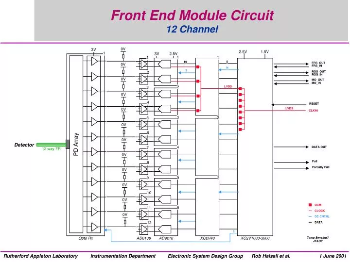
Front End Module Circuit 12 Channel. 0V. 3V. 2.5V. 1.5V. 1. 3V. 2.5V. 1. 1. 1. 5. 10. FRS_OUT. 0V. FRS_IN. N. 3. ROS_OUT. 2. ROS_IN. 0V. MO_OUT. MO_IN. 2. LVDS. 3. 0V. 4. RESET. LVDS. 0V. CLK40. 3. 5. 2. 0V. 6. 0V. PD Array. Detector. 4. DATA OUT. 7.

E N D
Front End Module Circuit12 Channel 0V 3V 2.5V 1.5V 1 3V 2.5V 1 1 1 5 10 FRS_OUT 0V FRS_IN N 3 ROS_OUT 2 ROS_IN 0V MO_OUT MO_IN 2 LVDS 3 0V 4 RESET LVDS 0V CLK40 3 5 2 0V 6 0V PD Array Detector 4 DATA OUT 7 12 way FR 0V Full 8 Partially Full 0V 5 9 3 0V 10 0V DCM 6 11 CLOCK 0V DC CNTRL 12 DATA 6 Opto Rx AD8138 AD9218 XC2V40 XC2V1000-3000 Temp Sensing? JTAG?
9U Board LayoutFront End Envelope 130 mm 270 mm 1 45 mm 366.7 mm 8
Front End Module Layout9U Envelope - Active Components 58 x 18 mm 27 x 27 mm FPGA XC2V1000- XC2V3000 FG676 Opto Rx PAROLI 45 mm 12 x 12mm FPGA XC2V40 CS144 9 x 9 mm ADC AD9218 ST48 33 x 40 mm 5 x 3 mm DIFF OP-AMP AD9218 RM8 Opto Rx NGK 45 mm Double Sided 130 mm Single Sided N.B. No Passives Shown