Download
1 / 32
320 likes | 462 Views
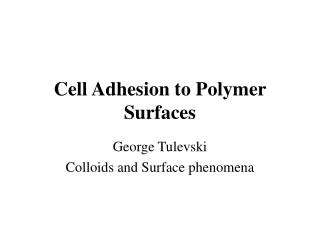
A novel MEMS platform for a cell adhesion tester. Ethan Abernathey Jeff Bütz Ningli Yang Instructor: Professor Horacio D. Espinosa ME-381 Final Project, Dec 1, 2006. Overview. Basic design Advantages of biaxial testing Stretcher coatings Manufacturing process Force calculation

E N D
A novel MEMS platform for a cell adhesion tester Ethan Abernathey Jeff Bütz Ningli Yang Instructor: Professor Horacio D. Espinosa ME-381 Final Project, Dec 1, 2006
Overview • Basic design • Advantages of biaxial testing • Stretcher coatings • Manufacturing process • Force calculation • Air and water operation • Summary
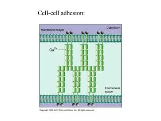
Structure • X structure applies biaxial force • 3 lower sections move (top stationary) • Driven by single comb drive actuator Return
Operation • Biaxial displacement within 5% • Displacement measured with optical microscope • 60 μN at driving voltage of 100 V • 3.4 μm displacement at 100 V (shown below)
Advantage of Biaxial Testing • Uniaxial testing causes large elongation • Stiffness may decrease with elongation • Biaxial testing allows for much smaller displacement and avoids decreasing stiffness
Advantage of biaxial testing • Possible method of displacement affecting cell stiffness • Buckling of inner cytoskeleton causes a more linear response
Advantage of Biaxial Testing • Linear response seen in graph A • Biaxial stretching can stop this behavior by eliminating lateral strain, seen in graph B
Stretcher Coating • Required force for cell detachment can be reduced • Coating with 1-dodecanethiol (DDT), 1-hexadecanethiol (HDT) and 1-octadecanethiol (ODT) on Au substrate can decrease detachment force (curve peaks)
Microfabrication • Based off of the PolyMUMPS fabrication process. • PolyMUMPS – Multi-User MEMS Processes • Provides fabrication of cost-effective, proof-of-concept MEMS devices • Multi-step process utilizing interchanging layers of polycrystalline silicon and a sacrificial layer (in this case Phosphosilicate Glass)
Doping and Insulation • n-type Si wafer is doped further to prevent charge feedthrough • An insulating layer of Si3N4 is deposited using LPCVD
PolyS 0 • Initial layer of Polycrystalline Silicon (PolyS 0) deposited with LPCVD • Photolithography to create support posts for device • Positive mask along with RIE to make pattern
PSG 1 • Sacrificial layers of PhosphoSilicate Glass (PSG) are used to provide intermediate layers • Can be patterned to surround the PolyS 0 features • Eventually will be removed to release structure
PolyS 1 • New layer of PolyS added in order to build the suspended cell stretching platform • Transverse bar seen at bottom of mask is actually connected to comb drive actuator
PSG 2 • Second sacrificial layer applied and patterned to surround platform features • Will provide support for final layer of PolyS
PolyS 2 • This layer of PolyS creates the linkage arms for the device • Four separate arms are used to connect the platform quadrants
Final Outcome • Side and Top Views • Linkage to comb drive can be observed
Comb Drive Actuator • Connects to the transverse bar of the test device • PolyS and PSG labels are the same as for test device fabrication • Analogous process to Cell Stretcher • Begins on same doped and insulated wafer
PolyS 0 • PolyS 0 layer creates the stator bases and the posts for the folded springs
PSG 1 • PSG is used to provide support for main comb drive structure
PolyS 1 • PolyS 1 layer creates both the rotor and stator heads and combs • Folded springs also come from PolyS 1 layer
Final Release of Device • The device is ready for release after PolyS 2 layer is applied • A ~49% HCl mixture in water is most effective etch to remove the PSG layers • Once PSG removed, the moving pieces of the device are freed
How to calculate x If small displacements are assumed, it can be inferred that ΔBx ≈ ΔCy / 2 ΔBy = ΔCy / 2 Δx = Δx0 + 2 ΔBx ≈ Δx0 + Δ Cy Δy = Δ y0 + 2 ΔBy = Δy0 + ΔCy Δx0, Δy0 : tip distances in the undeformed configuration.
How to calculate k • Six folded springs are connected to the central bar of the vertical moving structure of the device to provide restoring force • The spring stiffness Kb = 24EI / (l13 + l23) • The stiffness k of the “X” structure Kx ≈8 times the one of each single folded spring • K=6 Kb+Kx Structure
Comb drive is used to operate the cell stretcher • It has 12 sets of comb, each with 42 electrodes • The actuation force of a comb drive actuator F = NεtV2/g N : the number of comb electrodes, ε : the permittivity constant t : the comb electrode thickness V : the driving voltage g : the comb electrode gap.
In air operation • A DC power supply is wired to the support plate connectors. • Use a low-power, high output impedance power supply. • A high voltage generator to collect displacement information, while reading the actual voltage by means of a high input impedance multimeter. • To observe and record its behavior, the MEMS device is placed on the stage of an optical microscope equipped with a digital camera.
Underwater operation • Underwater challenges Electrolysis water is broken down into hydrogen and oxygen at the anode and cathode, respectively, can produce large amounts of gas underwater, which will lead to device failure due to bubbling Surface tension Water is prevented from flowing under the PolyS 1 layer, since the silicon-water interface tension is high, which in turn causes the silicon surface to behave hydrophobically Electrical conductivity If the medium is electrically conductive, current can bypass the actuators and the power available to the actuators is reduced, negatively affecting actuator efficiency.
Underwater solutions Ⅰ • Electrolysis Use AC driving system Consists of a signal generator a high-frequency ac square wave that was set to drive the comb with a 1 MHz square wave signal with an average voltage of 0 V.
Underwater solutions Ⅱ • Surface tension • Electrical conductivity Consider that surfactants can reduce the surface tension of water by adsorbing at the liquid-gas interface, we can add a surfactant (sodium laureth sulphate) to reduce the silicon-water interface tension till the silicon surface became hydrophilic. Using deionized water allowed the comparison of water properties such as thermal conductivity and dielectric constant without unusually large current bypassing the actuators.
Underwater operation • Performed applying a small drop of deionized water over the entire surface of the chip • Cover it with a microscope slide glass window. • The displacements are measured using the same optical equipment as in the air • An oscilloscope was used for the acquisition of the effective amplitude signal.
Summary • Biaxial cell stretcher design chosen for advantages of biaxial stress • Coatings chosen for ensured cell release • Manufactured using reliable polyMUMPS process • Able to operate in air and in water