Download
1 / 39
400 likes | 514 Views
TST-2. RF Start-up, Heating and Current Drive Studies on TST-2 and UTST. R 0.38 m a 0.25 m B f 0.3 T I p 0.2 MA. Y. Takase, TST-2 Team, UTST Team The University of Tokyo. The 15th International Workshop on Spherical Tori 2009

E N D
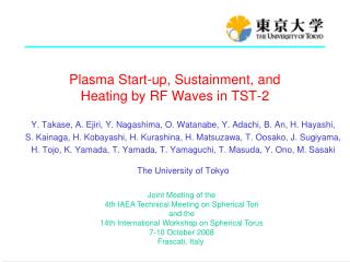
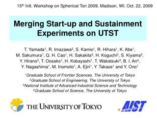
TST-2 RF Start-up, Heating and Current Drive Studies on TST-2 and UTST R 0.38 m a 0.25 m Bf 0.3 T Ip 0.2 MA Y. Takase, TST-2 Team, UTST Team The University of Tokyo The 15th International Workshop on Spherical Tori 2009 22-24 October 2009Madison, Wisconsin, U.S.A. UTST
Outline • Ip start-up experiments on TST-2 • High-harmonic fast wave (HHFW) experiments on TST-2 and UTST • Plan for LHCD experiment on TST-2
Ip Start-up Experiments on TST-2 • In TST-2, Ip start-up, ST plasma formation and sustainment have been achieved by EC power (up to 5 kW at 2.45 GHz). • When Ip reaches a critical value, Ip increases abruptly (current jump) and reaches a steady sustainment level Ipsus which is proportional to Bz. • Before current jump the field configuration is open. • After current jump an ST configuration with closed flux surfaces is sustained. • Once initial plasma is formed, RF power (up to 30 kW at 21 MHz) injected using the HHFW loop antenna can induce a current jump and sustain the ST configuration with the same Ipsus as the EC sustained case.
2-Strap HHFW Antenna(only 1 strap was used) TST-2 Spherical Tokamak and Heating Systems 21MHz, up to 400 kW (up to 30 kW was used) R = 0.38 m a = 0.25 m A = 1.5 X-mode launch horn antenna for ECH 2.45 GHz, up to 5 kW
0.1 z[m] 0 -0.1 0.4 -0.4 0 0 y[m] x[m] 0.4 -0.4 3 Phases of Ip Start-up by ECH 0.6 0.6 Open Field Lines Closed Flux Surfaces Current Jump 0 0 Ip increases rapidly once Ip reaches a critical level determined by Bv. -0.6 -0.6 0 0.5 0 0.5 0.4 particle orbit z[m] 0 -0.4 -0.4 0.4 0 0 y[m] x[m] 0.4 -0.4
Sustainment by RF Power Alone RF • Antenna excites a broad toroidal mode number spectrum, up to |nf| ~ 20. But only |nf| = 0, 1, 2 can propagate to the core. • Ion absorption is not expected due to high w/wci (> 10). Ion (H/D, C, O) heating was not observed (< 10 eV). • Electron absorption is expected to be weak due to low be. Soft X-rays (up to 3 keV) were observed at high RF power (~ 30 kW). RF only EC sust. RF sust. • RF (21MHz) power can induce a current jump. • Ip can be sustained by RF power alone.
Truncated Equilibrium Top limiter Truncation boundaries Outboard limiter Inboard limiter To treat finite pandjinthe open field line region,“truncated equilibrium” is used. [A. Ejiri et. al., Nucl. Fusion 46, 709-713 (2006).] R LCFS • The following effects are not taken into account: • anisotropic pressure • parallel pressure gradient Bottom limiter
Equilibrium Reconstruction Red: measurements Black: fit Distribution of Ieddy is pre-calculated for given Ip(t). Ieddy can become ~1/3of Ip during current jump. x10 Flux loops Saddle loops Pickup coils Vacuum field and locations of magnetic measurements
Evolution of Equilibrium appearance of closed flux surfaces (a) (b) (a) (b) (c) (c) #53783, t=40ms #53783, t=25ms #53783, t=50ms 0.4 0.4 0.1 Pressure [Pa] 0.0 0.0 0.0 8 10 1.0 p’ p’ p’ total jf [kA/m2] jf [kA/m2] jf [kA/m2] total total 0 0.0 0 ff’ ff’ -4 ff’ 0.6 0.6 0.6 0.4 0.4 0.4 y y y 0.2 0.2 0.2 LCFS LCFS Z [m] Z [m] Z [m] 0.0 0.0 0.0 jf jf jf -0.2 -0.2 -0.2 -0.4 -0.4 -0.4 -0.6 -0.6 -0.6 0.1 0.1 0.1 0.3 0.3 0.3 0.5 0.5 0.5 0.7 0.7 0.7 R [m] R [m] R [m]
Comparison of Equilibria during Sustainment RF sustained, Ip = 0.6 kA EC sustained, Ip = 0.6 kA EC sustained, Ip = 1.3 kA #53197 90ms #53773 50ms #53783 50ms Inboard limiter Inboard limiter Outboard limiter Inboard limiter LCFS Outboard limiter Outboard limiter LCFS LCFS Truncated boundary Truncated boundary Truncated boundary jj LCFS LCFS jj jj LCFS y y y
Velocity Space Structure in Vacuum Field 1.0 (a) D 0.8 (III) 0.6 A (IV) C v^ /v0 (I) 0.4 (II) Velocity space for orbits starting from R = 0.38 m for PF2+PF5 configuration B classes of particle orbits 0.2 F E 0.0 -0.2 0.0 0.2 0.4 0.6 0.8 1.0 1.2 v||/v0 A. Ejiri et. al., Nucl. Fusion 47, 403-416 (2007).
Effect of Ef on Particle Orbits in Start-up Plasma 0.6 Toroidal Field (t=35 – 40 ms) • Banana orbits under the influence of self-generated Ef are analyzed. • Angular momentum is conserved from axisymmetry • Banana particles are frozen to flux surfaces, and move with flux surfaces towards the low field side. • This movement causes kinetic energy and plasma current to decrease (inverse of Ware pinch). • Passing particles have short energy decay times. They are accelerated in the direction to reduce Ip. Movement of orbit is small. Ipstops increasing when closed flux surfaces are formed. 0.4 0.2 0.0 –3 mV/m -0.2 – 14 mV/m -0.4 -0.6 0.2 0.4 0.6 R [m]
Condition for Flux Conservation 1 0 mRVf 2 Pf, qRAf 0 time [ms] 10 3 2 1 3 Angular momentum conservation Flux conservation
D of Orbits in Velocity Space Trapped region Inverse of Ware pinch; DY = 0 Transition region Co Trapped: DY ~< 0, DR ~> 0 DY < 0, DR, DZ ~ 0 Counter moving Acceleration DY < 0, DR, DZ ~ 0 Co moving Deceleration Velocity normalized by V0=RWe pol Ef-field dominated region Mixed transition region Co Counter : DY < 0, DR < 0 Co Trapped: DY ~< 0, DR ~> 0,
Discussion of Current Drive Mechanism In addition to the precessional current of trapped particles, Pfirsch-Schülter current can give net toroidal current in the open field line region. #53783, t=50ms 0.4 Pressure [Pa] 0.0 Top limiter The vertical drift current (Id) returns partially through the plasma (IpZ) and partially throught the vacuum vessel (IVV). 8 V.V. RS/2 p’ Plasma total RpZ jf [kA/m2] Id IVV 0 IpZ V RVV ff’ -4 0.6 RS/2 Bottom limiter 0.4 650-150=400A Z 0.2 LCFS jvv jd f Because of the V.V. current, the poloidal current is always in the diamagnetic direction. Z [m] q jf 0.0 j|| jf -0.2 y -0.4 4V/1.5 A=3 W -0.6 0.1 0.3 0.5 0.7 R [m]
HHFW Experiments on TST-2 and UTST • Up to 300 kW of RF power at 21 MHz has been injected into TST-2 plasmas. Two-strap antenna excites HHFW with a wavenumber spectrum peaked at kf ~15 m-1 at the antenna. • When parametric decay instability (PDI) is observed, the Te increment becomes smaller, the edge density shows a rapid increase, and the impurity Ti increment increases. • Wave measurements by microwave reflectometry, electrostatic and electromagnetic probes are consistent with the HHFW pump wave decaying into the ion Bernstein wave (IBW) or the HHFW lower sideband, and the low frequency ion-cyclotron quasi-mode (ICQM). • The lower sideband power varies approximately quadratically with the local pump wave power, which becomes smaller as absorption of the pump wave by the plasma increases. • In UTST, direct wave measurements inside the plasma were made with a 2-D array of magnetic probes. • The measured wave field profile was roughly consistent with the result of TORIC full-wave calculation.
RF Diagnostics Bφ Bz Reflectometer center stack probes φ=-60° φ=-65° φ=-55° Semi-rigid Cable φ=-30° φ=-115° φ=0° φ=-120° strap φ=-125° 2cm 1 turn loop φ=30° Core (insulator) φ=55° Direction of B field to be measured φ=60° φ=65° Slit φ=155° S. S enclosure TOP VIEW φ=150° φ=145°
Parametric Decay Observed by Reflectometer reflectometer reflectometer reflectometer pump QM LS LS pump There is a threshold in pump wave power. → Parametric Decay Instability (PDI) Ion Cyclotron Quasi-Mode fci RF probe
Correlation Between PDI and Electron/Ion Heating outboard-limited outboard-limited inboard-shifted inboard-shifted Stronger PDI Less electron heating More ion heating
Spectral Broadening of the Pump Wave • Spectral broadening can occur by • scattering by density fluctuations • parametric decay instability • Spectral broadening becomes larger farther away from the antenna. • Downshifted and broadened pump wave was observed at the inboard wall.
UTST Experiment (Univ. Tokyo and AIST) PF Pair Coils Objectives: • High-b ST formation • by double-null merging • (DNM) • High-b ST sustainment • by additional heating: • NBI and RF HHFW antenna Magnetic probe array located 45 away toroidally from the antenna 0.7m 2m PF Pair Coils
RF B2 Profile Comparison HHFW field is stronger in the periphery for single-strap excitation. RF magnetic field strength is lower for double-strap excitation Single-strap excitation Double-strap excitation
Wavenumber Measurement Radial coherence Reference Reference Vertical coherence
Radial and Vertical Wavenumbers Frequency [MHz] Frequency [MHz]
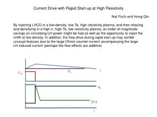
Plan for LHCD Experiment on TST-2 • Preparation is underway for lower hybrid (LH) current drive experiments on TST-2. • Up to 400 kW of power at 200 MHz will be used to ramp-up Ip from a very low current (~ 1 kA), very low density (< 1018 m-3) ST plasma. • Wave propagation and absorption were investigated using the TORIC-LH full wave code. • Core absorption is expected initially, but absorption is predicted to move radially outward with the increase in Ip and density.
Preparation for LHCD Experiment on TST-2 200 MHz transmitters Combline antenna (11 elements) (200 kW x 4, from JFT-2M) • Initially, the combline antenna used on JFT-2M, adapted for use on TST-2, will be used to excite a unidirectional fast wave with nf = 12 (corresponding to n|| = 5). • Direct excitation of the LH wave is planned in the future. • The fast wave can mode convert to the LH wave and drive current.
Collaboration with J. Wright, P. Bonoli (MIT) TORICLH/TST2/101/O ne0 = 1 x 10¹⁷ m-3 Te0 = 1 keV Ip = 10 kA n||0 = 7 qant = 0
TORICLH/TST2/101/U ne0 = 1 x 10¹⁷ m-3 Te0 = 1 keV Ip = 30 kA
TORICLH/TST2/101/M ne0 = 1 x 10¹⁷ m-3 Te0 = 1 keV Ip = 100 kA
TORICLH/TST2/102/A ne0 = 1 x 10¹⁸ m-3 Te0 = 1 keV Ip = 100 kA n||0 = +7 qant = 0
TORICLH/TST2/102/B ne0 = 1 x 10¹⁸ m-3 Te0 = 1 keV n||0 = +3
TORICLH/TST2/102/G ne0 = 1 x 10¹⁸ m-3 Te0 = 1 keV n||0 = -3
TORICLH/TST2/102/F ne0 = 1 x 10¹⁸ m-3 Te0 = 1 keV n||0 = -7
TORICLH/TST2/101/O ne0 = 1 x 10¹⁷ m-3 Te0 = 1 keV Ip = 10 kA n||0 = 7 qant = 0
TORICLH/TST2/102/P ne0 = 1 x 10¹⁷ m-3 Te0 = 1 keV n||0 = 7 qant = 90
TORICLH/TST2/102/Q ne0 = 1 x 10¹⁷ m-3 Te0 = 1 keV n||0 = 7 qant = -90
TORICLH/TST2/102/O ne0 = 1 x 10¹⁷ m-3 Te0 = 1 keV n||0 = 7 qant = 180
TORICLH/TST2/101/A ne0 = 5 x 10¹⁸ m-3 Te0 = 1 keV LH res. at x = -5 cm FW cutoff at x = -14 cm