Download
1 / 21
210 likes | 216 Views
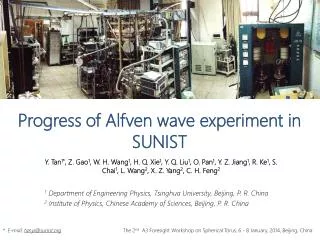
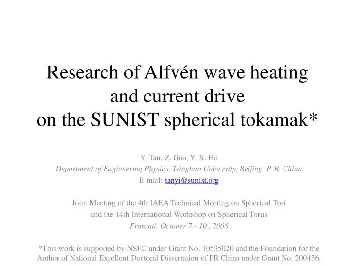
Research of Alfvén wave heating and current drive on the SUNIST spherical tokamak*. Y. Tan, Z. Gao, Y. X. He Department of Engineering Physics, Tsinghua University, Beijing, P. R. China E-mail: tanyi@sunist.org Joint Meeting of the 4th IAEA Technical Meeting on Spherical Tori

E N D
Research of Alfvén wave heating and current driveon the SUNIST spherical tokamak* Y. Tan, Z. Gao, Y. X. He Department of Engineering Physics, Tsinghua University, Beijing, P. R. China E-mail: tanyi@sunist.org Joint Meeting of the 4th IAEA Technical Meeting on Spherical Tori and the 14th International Workshop on Spherical Torus Frascati, October 7 - 10 , 2008 *This work is supported by NSFC under Grant No. 10535020 and the Foundation for the Author of National Excellent Doctoral Dissertation of PR China under Grant No. 200456.
Introduction • Objectives • Try to apply power low frequency waves (<wci) on ST plasmas • Experimental verification of Alfvén wave (AW) heating and/or current drive for ST plasmas • Motivations • (…have been presented by Prof. Z. Gao)
The SUNIST Spherical Tokamak Main Parameters R: 0.30m a: 0.23m Aspect ratio: ~1.3 Elongation: ~1.6 Bt0: 0.15T Poloidal flux swing: 60mV.s Ip: ~50kA 1440 Compensator Overview of SUNIST PF Coils V.V. 492 1260 600 TF Coils 300 CS The unusual vacuum vessel Cross section of SUNIST (mm) 100kW/2.45GHz Microwave Source
Task list • Impedance analysis • RF generator design & manufacture • Basic antenna design • Realization of the antenna system • Preliminary test • Installation • Experiments… this presentation
Part II 1-D MHD ANALYSIS BEFORE DESIGNING THE EXPERIMENTAL SYSTEM
AW resonances in SUNIST a=23 cm
Vacuum Vessel (a) (b) Return Limb Straps Plasma Basic concepts • Obviously, the unfolded concept is better than the folded one in efficiency. But the occupancy in windows and the connectivity to RF generators should also be concerned. folded, double layer unfolded, single layer reference: the preliminary design of AW antenna for the ETE spherical tokamak ( L. F. Ruchko and R. M. O. Galvao, 2004 )
The model for analysis rw rb IV ra Plasma rp R z Antenna I II III J’ Return Limb (folded concept) r θ J Vacuum Vessel -J • Te = 0 • Axisymmetrical, 1-D • Quite simple but far different from the actual shape of ST plasmas • Still available to get a quick estimation of the impedances Bz ~ constant n q O R
EM field equations (region I) K. Appert and J. Vaclavik, 1982. Only B∥ and E⊥ are concerned. m and n are toroidal and poloidal wave numbers respectively
EM field equations (region II, III & IV) • Only Bz is concerned • The distribution of Bz is quasi-magnetostatic • (low frequency, λ >> a, R) IV I II III J’ J -J
Boundary condition • r=0(initial value of integration) • r=rp (I-II): • r=ra (II-III): • r=rb (III-IV): • r=rw : IV K. Appert, et al., 1984 I II III J’ J L. F. Ruchko, et al., 1996 -J
Results (1) • Impedance(f), rRES(f) for the main modes (unfolded concept)
Results (2) • The degradation caused by the return limb of folded antenna • lose 70% impedance ( but is still acceptable for SUNIST) • To maximize the efficiency of the folded antenna • launching face: as close as possible to the plasma column • return limb: as close as possible to the wall of VV f=0.4 MHz, M=-2, N=1, the influence of the position of return limb
Harmonics of the antenna current plasma VV a R Straps
Impedance spectrums The spectrums and the radial distributions of impedance for two working points
Following guidelines are given by the rough analysis • a RF generator with an output frequency range of 0.4~1 MHz is enough for our experiments • the impedance of SUNIST plasmas varies from 0.1~0.5 Ohm • the space between the launching strap and the return limb of the folded antenna should be as large as possible to get higher efficiency Part III THE DESIGN AND MANUFACTURE OF THE EXPERIMENTAL SYSTEM
The realization of the antenna Arc Insulated bolt (M6) Few spare space available for antennas VV Return limb Must keep this window clear • To simplify manufacture • Arc to straight • To keep electrical insulation • The width of return limb is limited Plasmas Ceramic feed through Launching strap Straight Launching strap: 1 mm x 150 mm Return limb: 1 mm x 50 mm Stainless Steel
Assembling and preliminary test of the antenna L: 0.3 uH, R: 11 mOhm. 500 A / 250 kHz test passed. No mechanical vibration observed (fm<<fRF). Ceramic washer, the most uncertain point. 2.5 kV test passed @ 1 atm. But how it will be in vacuum with some plasmas? Double M6 nuts, TIG welded on the wall of VV. Minimum residual effects when antenna is not installed. Totally 8 modules will be installed in the VV
Shield or limiter • No shield or limiter will be attached at the first step of experiments • Limiters (BN plate or insulated SS plate) will be directly attached on the launching straps in the next step Launching strap Field line Limiter VV Insulated fixer Limiter Return limb
RF generator Transmission line & the antenna Resonant circuit Four tubes 4-phase testing • 4x100 kW/0.4~1 MHz, four phases • Status: four phase output tested for 4x10kW, but still stored in the factory Equivalent load
Summary • The impedances and the frequency range of certain AW modes in SUNIST have been estimated by a simple 1-D MHD analysis . • The experimental system is setup following the analysis. • There remain uncertainties. We are crossing the river by feeling the stones. Comments, suggestions and questions are welcome.