Download
1 / 41
410 likes | 557 Views
Beam induced RF heating. Benoit Salvant, with the invaluable input and help of many colleagues:

E N D
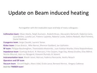
Beam induced RF heating Benoit Salvant, with the invaluable input and help of many colleagues: Collimation team: Oliver Aberle, Ralph Assmann , Roderik Bruce, Alessandro Bertarelli, Federico Carra, Marco Garlasche, Luca Gentini, Luisella Lari, Stefano Redaelli, Belen Salvachua, Marc Timmins, Cryogenics team: Serge Claudet, Laurent Tavian and Cryo operators Experiments: Mario Deile, Sune Jakobsen Injection team: Chiara Bracco , Mike Barnes, Wolfgang Bartmann, Brennan Goddard, Volker Mertens, Jan Uythoven RF team: Philippe Baudrenghien, ThemistoklisMastoridis, Juan Esteban Mueller, Elena Shaposhnikova Impedance team: Gianluigi Arduini, Olav Berrig, Fritz Caspers, Hugo Day, Alexey Grudiev, Oleksiy Kononenko, Elias Métral, Nicolas Mounet, Jean-Luc Nougaret, Serena Persichelli, Giovanni Rumolo Instrumentation team: Enrico Bravin, Rhodri Jones, Mariusz Sapinski, Andriy Nosych, Federico Roncarolo LHC Operators and operation team MPP team: Rudiger Schmidt, Jorg Wenninger, Daniel Wollman, Markus Zerlauth Vacuum team: Vincent Baglin, Giuseppe Bregliozzi, Alexis Vidal, Giulia Lanza, Bernard Henrist, Gregory Cattenoz And the TIMBER team!
Main messages of this talk • Heating continued to be an issue in 2012 on many LHC devices, and significantly affected operation. • Heavy upgrades are planned on most affected hardware during LS1. • It is not clear that the upgrade foreseen for the TDI will be enough to be safe until the new design comes in LS2. • Choice of parameters after LS1 from heating point of view: • The longer the bunches the better • The longitudinal distribution plays a very important role for some devices, and it should be kept under tight control (in particular during the ramp) • 25 ns or 50 ns bunch spacing is expected to be similar for most equipment with currently planned parameters. However, we need to watch for surprises. • More temperature monitoring is needed on critical devices.
Agenda • RF heating? • Status at Chamonix 2012 • Observations and limitations during the 2012 run • Expectations for after LS1 • Summary
Beam induced RF heating? Intensity Temp tube MKI8C Energy Temp TCPB6L7 Temp MKI8C Temp ALFA • Example of temperature increase for kicker, collimator, detector during 4 LHC fills in mid Nov 2012 • Temperature increase believed to be due to the interaction of beam induced wake fields with the surrounding also referred to as “RF heating” • Temperature increase in LHC devices can cause several issues (damage, delays, dumps) • Other sources of heating of beam surrounding : synchrotron light, beam losses, electron cloud (not addressed during this talk)
Agenda • RF heating? • Status at Chamonix 2012 • Observations and limitations during the 2012 run • Expectations for after LS1 • Summary
Status at Chamonix 2012 • Topic followed-up since first observed limitations in 2011 • Mini-Chamonix June 2011 (Jan Uythoven) • Evian December 2011 (Benoit Salvant) • Chamonix February 2012 (Elias Métral) • C-MAC August 2012 (Elias Métral) • LMC148 September 2012 (Benoit Salvant) • LMC152 October 2012 (Elena Shaposhnikova RF manipulations to reduce heating) • LMC155 October 2012 (Benoit Salvant) • LMC159 and TE/TM December 2012 (Elias Métral conclusions of RF fingers task force) • Conclusions from Chamonix 2012 (Elias Métral) and 2012 observations It did not really get better in 2012…
Status at Chamonix 2012 • Topic followed-up since first observed limitations in 2011 • Mini-Chamonix June 2011 (Jan Uythoven) • Evian December 2011 (Benoit Salvant) • Chamonix February 2012 (Elias Métral) • C-MAC August 2012 (Elias Métral) • LMC148 September 2012 (Benoit Salvant) • LMC152 October 2012 (Elena Shaposhnikova RF manipulations to reduce heating) • LMC155 October 2012 (Benoit Salvant) • LMC159 and TE/TM December 2012 (Elias Métral conclusions of RF fingers task force) • Conclusions from Chamonix 2012 (Elias Métral) and 2012 observations It did not really get better in 2012…
Agenda • RF heating? • Conclusions from Chamonix 2012 • Observations and limitations during the 2012 run • VMTSA • TDI • MKI • TCP.B6L7 • ALFA • Q6R5 • BSRT • TCTVB • Expectations for after LS1 • Summary
Double-bellow module VMTSA • 8 bellows (out of 20) were found damaged in November and December 2011. • Hard work of TE/VSC and the LRFF working group mandated since then to understand issues with LHC RF fingers:Simulations and measurements showed that there is no problem if good contact is ensured consolidation of the design to avoid bad contacts 8 modules reinstalled with new shorter RF fingers, ferrite plates and reinforcement corset no problem since then (both on vacuum gauges and temperature) • Plans for LS1: remove all these modules and identify others that could fail Believed to be solved Reinforced corseted fingers installed in 2012 Damaged module Old fingers Courtesy: Vincent BaglinTE/VSC (LMC 16/11/2011) Courtesy: Bernard Henrist TE/VSC
Agenda • RF heating? • Conclusions from Chamonix 2012 • Observations and limitations during the 2012 run • VMTSA • TDI • MKI • TCP.B6L7 • ALFA • Q6R5 • BSRT • TCTVB • Expectations for after LS1 • Summary
Injection protection collimator TDI (status Feb 2012) • The 2 TDI beam screens were found damaged by EN/STI, TE/VSC and BE/ABP after the 2011 run. • Temperature, vacuum, jaw deformation during the run suggested significant heating as the TDIs were not retracted to parking position • Electromagnetic simulations by BE/ABP, BE/RF and EN/MME confirm that the heating can be significant. It is however not completely clear that beam induced heating alone generated the damage. • Both TDIs were left in that state and a reinforced spare was prepared by EN/STI. • A temperature probe was planned to be installed to monitor the temperature of the beam screen but it was decided to remove it after a problem during the bake-out. Deformation of the beam screen A. Grudiev, M. Timmins TDI jaw
Pressure observations at TDI during 2011 and 2012 Overview of 2011-2012 2011 2012 Pressure at TDI.4L2 Pressure at TDI.4R8 August 2011 Strong heating on both TDIs suspected (before TDI at +/-55 mm in physics) May 2012 No heating November 2012 Heating came back on TDI.4L2? (situation since mid-August 2012)
Injection protection collimator TDI (status Dec 2012) • Suspicious pressure curves could indicate that additional heating occurs in or close to the TDI4L2 since mid-2012. • Many mechanical issues on both TDIs towards the end of the 2012 run (see talk of Chiara Bracco): did the RF heating make things worse? • Current plans for LS1: reinforce beam screen (TDI design meetings). • Will that be enough in view of the recent problems? Resistive wall contribution for the TDI vs gap Parking position in 2011 (+/- 20 mm) 90 W This contribution could be strongly reduced (<1W) by a thin copper coating. feasible? Parking position in 2012 (+/- 55 mm) 30 W N. Mounet Potential actions to be discussed with all stakeholders
Agenda • RF heating? • Conclusions from Chamonix 2012 • Observations and limitations during the 2012 run • VMTSA • TDI • MKI • TCP.B6L7 • ALFA • Q6R5 • BSRT • TCTVB • Expectations for after LS1 • Summary
Injection kicker MKI • MKI regularly delays injection after a dump by up to a few hours (most critical was MKI8D and from TS3 onwards, MKI8C). • EM simulations and measurements and thermal simulations are consistent with observations (despite the very high complexity of the device). • Extensive studies within the MKI strategy meetings to: • Reduce the electric field on screen conductors (P. Adraktas, M. Barnes) • Reduce the longitudinal impedance yielded new design of the screen conductors (M. Barnes, H. Day et al) • Improve heat radiation from the ferrite increase tank emissivity (M. Barnes, M. Garlasche et al) • The removal of selected bake-out jackets reduced measured magnet temperature by resp. 3 deg C to 7 deg C on MKI8B and MKI8D. The jackets on MKI2B and MKI2D were removed on 11 Sept. However it is preferred, in the future, to keep the bake-out jackets ON the tanks. H. Day Bake-out jacket Courtesy: Mike Barnes TE/ABT
Injection kicker MKI8D • Bench measurements and simulations predict that the new MKI design (19 conductors)would better screen the ferrite from the beam than the current MKI design (15 conductors)(M. Barnes, H. Day et al) • During TS3, the MKI8D was replaced with a spare with 19 screen conductors, 15 conductors 19 conductors H. Day TS3 • Clear improvement for the replaced kicker with more screen conductors • Promising for the upgrade of all MKIs in LS1.
Injection kicker MKI8C However, after this same TS3, it was realized that MKI8C was limiting, and it was traced to a large temperature on the tube (up to 180 degrees). • Analysis of kicker rise time and delay shows that the kicker performance is not observed to be affected by the increase of temperature on the probes (M. Barnes). • A plausible hypothesis is that the additional source of heating is not the magnet ferrites but lies next to the “tube Up” probe. the interlock level for that magnet was increased accordingly, and the limit was increased We’ll look for anomalies when opening MKI8C in LS1. MKI8C tube PT100 Tube_Up MKI8B tube PT100 Mag_Up MKI8C magnet MKI8B magnet
Injection kicker MKI: plans for LS1 • Follow-up closely by the MKI Strategy meeting • All MKIs are planned to be upgraded and the beam impedance measured during LS1, aiming at • reducing the longitudinal impedance by improving the screening of the ferrite from the beam aim at 24 screen conductors (instead of 15 or 19 screen conductors) reducing the high electric field of the screen conductors (tests planned early January to confirm promising results from simulations (M. Barnes)) Impedance bench measurements on a smaller scale setup planned early January to confirm promising results from simulations (H. Day) • Improving the radiation of heat by increasing the emissivity of the tank (tests of a prototype on-going) active cooling with fluid very difficult to envisage due to high voltage operation. • reducing the likelihood of a spark from the beam screen conductors • suppressing the anomalous heating presently exhibited by MKI8C Many actions taken for after LS1, and promising New design for 24 screen conductors (H. Day and M. Barnes)
Agenda • RF heating? • Conclusions from Chamonix 2012 • Observations and limitations during the 2012 run • VMTSA • TDI • MKI • TCP.B6L7 • ALFA • Q6R5 • BSRT • TCTVB • Expectations for after LS1 • Summary
Primary skew collimator TCP.B6L7.B1 • TCP.B6L7.B1 caused dumps in 2011 and 2012, and the steady increase of its jaws’ temperature during physics fills with increasing intensity required increasing the interlock to 95 degrees. • The temperature of all other primaries (including its symmetric for B2) increases only by 1 degree. • Joint analysis of heat deposition and measured temperatures by EN/MME and BE/ABP points to an absence of efficient cooling (suspected non-conformity). • Beam induced heating clearly observed but heating also due to losses • Nothing wrong was seen with visual and X-ray inspections by EN/STI and EN/MME on both cooling systems and RF fingers. • Plans for LS1: thorough check of the cooling system (EN/STI and Collimation WG). Non conformity of cooling should be solved Bunchlength Intensity Temp TCP.B6L7 Kinks due to losses Energy TCP.B6L7 gap
ALFA roman pot • The ALFA detectors’ temperature reached 42 degrees and bordering the range that is expected to lead to detector damage (45 degrees). • Joint studies by BE/ABP and ATLAS-ALFA showed that the temperature increase is consistent with impedance heating of the ferrite damper ring (which is efficiently preventing more harmful heating). • The TOTEM detector does not have this problem as it was designed with active cooling of the detector. • As emergency measures, the ALFA team removed the bake-out jackets and added some fans. • Plans: implement a new design with reduced impedance and active cooling during LS1. Significant refurbishment planned fans Courtesy: S. Jakobsen (ALFA)
Beamscreentemperatureregulation • Until TS3, standalone Q6R5 had no margin for more cooling. This could have been an issue for 7 TeV operation. • Tests were performed (Xrays on both bellows and cooling circuit) and so far nothing special was seen that could explain the singularity of Q6R5. • Since September 2011 (TS3), the situation improved significantly. Only a few fills have been affected since then, in particular the fills following a movement of the neighboring TOTEM roman pot, indicating a possible correlation (through vacuum or losses or both). This is under study with the TOTEM, TE/VSC and TE/CRG teams. • During LS1 the valves for standalones will be replaced to allow a higher cooling flux. May 2012,almost every fill required large regulation of Q6R5 Need for more cooling On the following fill TOTEM movement Valve opening of Q6R5 regulation November 2012 almost no fill affected Pressure in 6R5
BSRT • The B2 BSRT mirror and support suffered from damage that could be due to significant heating. • Simulation studies have been underway since June. Combined effort between BE-BI, BE-ABP, BE-RF and EN-MME to understand the heat deposition and to assess whether the Curie temperature of the ferrite has been reached. Still no clear conclusion, need to check impedance simulations with bench measurements in January • Temperature is measured from outside Need for temperature monitoring closer to the arm and the ferrite (planned to be installed during this Christmas stop). Would be useful to check high intensity 50 ns planned before LS1 • Heavy effort required and planned during LS1 to find a robust design. New design planned Bunch length B1 Beam intensity B1 Temp BSRT B1 Temperature bellow BSRT B1 Bunch length B2 B2 Temp BSRT B2 BSRT B1 IN BSRT B1 OUT Temp BSRT B2 BSRT heating increases with smaller bunch length Much less heating in the out position (ΔT is divided by 3)
2- beam Tertiary collimators TCTVB.4R8 and 4L8 • Despite active cooling, TCTVBs in IR8 consistently heat by around 10 degrees • Already mentioned at mini-Chamonix but the worst TCTVB was taken out in 2011 • beam dump by TCTVB.4L8 temperature when longitudinal blow up stopped working on May 30th Worry if bunch length is reduced in physics, but should be replaced by TCTPs after LS1 Removed 1.2 ns 0.85 ns
Agenda • RF heating? • Conclusions from Chamonix 2012 • Observations and limitations during the 2012 run • Expectations for after LS1 • Beam parameters • Elements planned to be installed in LS1 • Summary
What lies ahead of us? • After LS1: current situation (50 ns) at 6.5 TeV or nominal beam at 6.5 TeV: • Larger total beam intensity (25 ns spacing) • Smaller bunch intensity 1.15 1011 p/b bunch length ? • current ? (1.2 to 1.3 ns) • Nominal ? (1ns) Effect of 25 ns and bunch length on RF heating?
Computing power loss • Power lost by the beam in a device of impedanceZlong(see E. Métralat Chamonix 2012): M=2808 bunches Nb=1.15 1011 p/b Power spectrum measured on 50 ns by P. Baudrenghien and T. Mastoridis Impedance Re(Zlong) of TCP in physics Narrow band at fres broadband
Effect of 25 ns on RF heating? • Power lost by the beam in a device of impedanceZlong(see E. Metral at Chamonix 2012): • Assumptions: same bunch length and same bunch distribution for 50 and 25 ns spacing same beam spectrum but with half of the peaks M=2808 bunches Nb=1.15 1011 p/b Impedance Re(Zlong) Narrow band at fres broadband switching to 25 ns for broadband: increase by factor switching to 25 ns for narrow band falling on a beam harmonic line (fres= k*20 MHz): increase by factor (if fres=2*k*20 MHz) or 0 (if fres=(2*k+1)*20 MHz)
Effect of bunch length on RF heating? • Power lost by the beam in a device of impedanceZlong(see E. Metral at Chamonix 2012): • Assumption: same bunch distribution for 25 ns and 50 ns beam spectrum is extended to higher frequencies with an “homothetic” envelope M=2808 bunches Nb=1.15 1011 p/b Impedance Re(Zlong) Narrow band at fres σ=1 ns σ=1.25 ns broadband • switching to lower bunch length for broadband: • in general regularly increases (depends on broadband resonant frequency) switching to lower bunch length for narrow band: enhances some resonances , damps others, excites higher frequency resonances From the heating point of view, the longer the bunch the better in most cases.
Available data to predict situation after LS1? • Fills with stronger heating on B2 on ALFA and BSRT (Oct 26th to Oct 28th ) • Results from OP test on bunch length reduction (Nov 29th) • Results from MD on flattening bunches (Nov 29th) • Need more time for the analysis, very promising method to reduce heating • Results from scrubbing (December) • Need to disentangle heating from electron cloud and from impedance
Fills with stronger heating on B2 (Oct 26th to Oct 28th ) Temp ALFA B2 ALFA temperature Temp ALFA B1 Strong changes of beam spectra at flat top from fill to fill: - High frequencies were much worse for B2 on Oct 27th than after - This difference is believed to be due to the different action of the longitudinal blow up during the ramp on B1 and B2 - significant increase of temperature on BSRT too
Fills with stronger heating on B2 (Oct 26th to Oct 29th) Preliminary power loss computed from spectra and simulated impedance of ALFA along the fills ramp Top energy ramp Top energy Around 10 W more on B2 than B1 at top energy (+40% power loss on ALFA B2) B1 and B2 are similar It is critical to control the beam spectrum!
Results from the bunch shortening test Simulations of power loss from the spectra measured during the test for ALFA, MKI and BSRT Example of a measurement:Measurement of average temperature of all arcs during the test - Measured bunch length (measured) injection Measured arctemperature injection The test confirmed that shorter bunch length increases heating for most monitored devices We stayed 1h between 1 ns and 1.1 ns with 1380 bunches at 1.5 1011 p/b without major issue
Bunch length test summary • Very different patterns with bunch length, helps to understand the origin of the heating • The items that heated more are planned to be upgraded (ALFA, MKI8C, TDI, BSRT) or removed (TCTVB) • No hard showstopper unveiled by this test to run at lower bunch length
Elements planned to be installed in LS1 • Tertiary collimators replaced by new design with BPMs (issues with ferrites) • Secondary collimators in IR6 replaced by new design with BPMs • Smaller radius for experimental beam pipes • new LHCb VELO (LS2) • New forward detectors around ATLAS and CMS (AFP and HPS) • Modifications in view of installation of the forward detectors in 2015 • Improved roman pots (both ALFA and TOTEM) • Improved BSRT, TDI, MKI, TCP.B6L7. • UA9? • Recall of general guidelines to minimize power loss • need for efficient cooling of near-beam equipment to avoid what has happened to TDI, BSRT and ALFA (from F. Ruggiero, L. Vos) • Maximize evacuation of heat (optimize emissivity, thermal conduction) • Need to ensure good RF contact to avoid what happened to VMTSA (LLRF WG guidelines) • Use high Curie temperature ferrites whenever possible (e.g. Transtech TT2-111R, but beware of vacuum compatibility) • Need for more monitoring of temperature inside critical equipment (e.g.: TDI, BSRT, TOTEM pot)
Agenda • RF heating? • Conclusions from Chamonix 2012 • Observations and limitations during the 2012 run • Expectations for after LS1 • Summary
Summary • Many devices are heating at a faster rate following the bunch intensity ramp-up • Actions are/should be planned to be taken in LS1 to prepare safe and smooth running: • Efficient cooling for all near beam equipments (in particular BSRT, TDI, ALFA) • Consolidation of RF contacts (see conclusion of LRFF working group) • Analysis of suspected non-conformities (TCPB6L7, MKI8C, Q6R5 and TOTEM) • Systematic analysis of available pressure and temperature stored to detect other issues • Installation of more temperature monitoring of critical equipment • Control the longitudinal beam distribution and (if possible) optimize it to reduce heating • Since most heating devices have a dominating broadband impedance, the operation with 25 ns is expected to lead to slightly larger power loss (for the same bunch length, bunch distribution and nominal bunch intensity) • TDI and maybe BSRTs which also exhibit large narrow band impedance should be monitored closely. Other devices might start suddenly heating much more if the distribution changes. • From heating point of view, the main worries for after LS1 seems to be: • The extent of the upgrade of the TDI • the operation with nominal bunch length (~1 ns, compared to ~1.2-1.3 ns) • Uncontrolled longitudinal beam distribution during the ramp
Summary table LS1 will be busy!
Summary so far Computations with code of N. Mounet and CST/HFSS simulations data with H. Day, A. Grudiev, O. Kononenko, A. Nosych