Download
1 / 37
380 likes | 386 Views
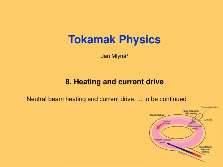
Tokamak Physics Jan Mlynář 8. Heating and current drive. Neutral beam heating and current drive, ... to be continued. Neutral Beam Injection: principle. Beam duct. Ion source. Accellerator. Neutraliser. Neutral beam. Magnetic filter. Ionisation. Thermalisation.

E N D
Tokamak Physics • Jan Mlynář • 8. Heating and current drive Neutral beam heating and current drive, ... to be continued 1: Úvod, opakování
Neutral Beam Injection: principle Beam duct Ion source Accellerator Neutraliser Neutral beam Magnetic filter Ionisation Thermalisation Electricity -> other form (kinetic energy of particles) Transport to plasma (outside part) (inside part)
NBI Principle, in more detail I E Day
Neutral beam heating = 2.9.1017 8: Heating and current drive
Neutral beam heating 8: Heating and current drive
Neutral beam heating 8: Heating and current drive
Beam slowing 8: Heating and current drive
Distribution function 8: Heating and current drive
Beam current drive 8: Heating and current drive
R Resonance zone Wave heating Antenna Wave to particles Electricity -> other form (electromagnetic oscillations) Transport to plasma (outside part) transmission lines antenna (inside part) waves Thermalisation
phase velocity fast slow direction of propagation k parallel to B0: according to polarisation (with respect to B0, in other fields of science –e.g. optics- wrt propagation direction) right -> direction of rotation of electrons left -> direction of rotation of ions k perpendicular to B0 ordinary: E1 // B0 extraordinary: E1 perp to B0 Classification of waves
Wave Heating Review of Plasma Waves 8: Heating and current drive
Wave Heating Dielectric Tensor 8: Heating and current drive
Wave Heating Classification of waves 8: Heating and current drive
Wave Heating Resonances, Cut-offs 8: Heating and current drive
Wave Heating Resonances, Cut-offs 8: Heating and current drive
Wave Heating Energy flow 8: Heating and current drive
Wave Heating: Ray tracing 8: Heating and current drive
Wave Heating: Ray tracing ASDEX-U 8: Heating and current drive
Wave Heating: Ray tracing Mode conversion Boundary conditions 8: Heating and current drive
Wave Heating: CMA diagram In each region, the topological form of thephase velocity remain unchanged. Fast wave is outside (the wave front in vacuum which would always be a circle) slow wave is inside. E.g. in the top left region (high B, low n) the X/L wave is slow, the O/R wave is fast(X and O have k || B, L and R have k ┴ B) 8: Heating and current drive
Ion Cyclotron Heating fast wave ~ tens of MHz Plasma edge cutoff below on harmonic frequencies heating on minorities (e.g. on H in D plasmas) Resonant layer is vertical at Heating on harmonics energies often higher than Ec relaxation is mostly due to heating of electrons 8: Heating and current drive
Ion Cyclotron Heating 8: Heating and current drive
Ion Cyclotron Heating Heating on minorities: Decreases with increasing concentration, however, new “ion-ion” hybrid resonance emerges. May result in IBW (Ion Bernstein Wave) can drive electrons Disadvantage: strongly sensitive on minority concentration ICRH advantages: Economic, powerful, important ion heating disadvantages: high E, problems with reflected power (ELMs), (“coupling of waves to plasma”, in particular problems with ELMs), non-directional. 8: Heating and current drive
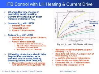
Lower Hybrid Resonance Slow wave at a small angle to B ~ GHz long path to the resonant region Landau damping along the path turns out to be more important than LH itself Plasma edge – evanescent region (cutoff below ) i.e. “waves tunnels through” The antenna produces a wide spectrum wide spectrum of fast electrons due to the Landau damping current drive Reminder: The current drive would not exist if distribution of velocities of plasma particles were flat. However, Maxwellian distribution is not flat, which means wave can locally flatten the distribution in the direction of the wave propagation. 8: Heating and current drive
Lower Hybrid Resonance 8: Heating and current drive
Mode converter • Equally split the RF power in 3 in the poloidal direction • 1 input & 3 outputs WR-229 • Conversion efficiency: 98.65 % • Return Loss: -20.5dB J. Hilairet
LH - Wave Propagation Depends on ne and B Antenna structure
Electron Cyclotron Resonance Advantages : no evanescent region highly directional highest achievable power density Disadvantages: acts only on electrons expensive new technology (less reliable) Highly directional profile control e.g. suppression of NTMs (mg. islands) 8: Heating and current drive
Electron Cyclotron Resonance 8: Heating and current drive
Electron Cyclotron Resonance 8: Heating and current drive
Electron Cyclotron Resonance Current Drive (ECCD) • Fisch – Boozer • directional increase of decreases n • Ohkawa • increase of pushes passing particles • into the trapped region (opposite direction to the Fisch - Boozer) lower momentum loss Other applications of ECR: • plasma heating • current profile control for advanced regimes • transport studies via modulated ECRH • plasma start-up assistance • wall conditioning (ITER) 8: Heating and current drive
Bulk and Tail Current Drive 8: Heating and current drive
ITER ECR system 24 x 1 MW, 170 GHz gyrotrons 3 x 1 MW, 120 GHz gyrotrons for SUA wave guide switch to … equatorial or upper launcher 8: Heating and current drive
ITER ECR Upper Port • 3 ports with 8 beams in two rows • Main function: NTM (and sawtooth) control • Front steering • In vertical direction to scan radial deposition • Well focussed for optimised localization at q=3/2 and 2 8: Heating and current drive