Download
1 / 31
320 likes | 477 Views
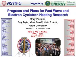
NSTX-U. Supported by. Plans for Wave Heating and Current Drive Research in the NSTX-Upgrade. Gary Taylor 1

E N D
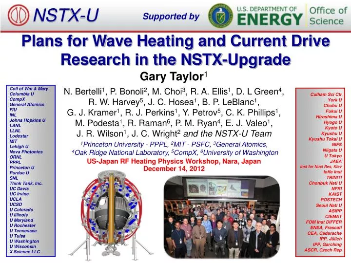
NSTX-U Supported by Plans for Wave Heating and Current Drive Research in the NSTX-Upgrade Gary Taylor1 N. Bertelli1, P. Bonoli2, M. Choi3, R. A. Ellis1, D. L Green4, R. W. Harvey5, J. C. Hosea1, B. P. LeBlanc1, G. J. Kramer1, R. J. Perkins1, Y. Petrov5, C. K. Phillips1, M. Podesta1, R. Raman6, P. M. Ryan4, E. J. Valeo1, J. R. Wilson1, J. C. Wright2and the NSTX-U Team 1Princeton University - PPPL, 2MIT - PSFC, 3General Atomics,4Oak Ridge National Laboratory, 5CompX, 6University of Washington Coll of Wm & Mary Columbia U CompX General Atomics FIU INL Johns Hopkins U LANL LLNL Lodestar MIT Lehigh U Nova Photonics ORNL PPPL Princeton U Purdue U SNL Think Tank, Inc. UC Davis UC Irvine UCLA UCSD U Colorado U Illinois U Maryland U Rochester U Tennessee U Tulsa U Washington U Wisconsin X Science LLC Culham Sci Ctr York U Chubu U Fukui U Hiroshima U Hyogo U Kyoto U Kyushu U Kyushu Tokai U NIFS Niigata U U Tokyo JAEA Inst for Nucl Res, Kiev Ioffe Inst TRINITI Chonbuk Natl U NFRI KAIST POSTECH Seoul Natl U ASIPP CIEMAT FOM Inst DIFFER ENEA, Frascati CEA, Cadarache IPP, Jülich IPP, Garching ASCR, Czech Rep US-Japan RF Heating Physics Workshop, Nara, Japan December 14, 2012
Outline • Introduction • Long-Term Research Thrusts (5-10 years) • Near-Term Research (2-3 years) • Tools Supporting RF Research: • RF Simulation Capabilities • EC/EBW Heating System • Diagnostics & Other Facility Upgrades • Summary 2
Outline • Introduction • Long-Term Research Thrusts (5-10 years) • Near-Term Research (2-3 years) • Tools Supporting RF Research: • RF Simulation Capabilities • EC/EBW Heating System • Diagnostics & Other Facility Upgrades • Summary 3
NSTX-Upgrade will address critical spherical torus (ST) plasma confinement and sustainment issues • Center stack diameter increases from 2040 cm; providing 2x Ip and BT(0), and 5x the pulse-length of NSTX (~5 s) • Neutral beam injection (NBI) power will increase from 612 MW, with addition of three larger tangency radius beam lines • Reduced collisionalitywill allow access to a regime relevant to a Fusion Nuclear Science Facility ST (FNSF-ST) • 100% non-inductive current drive (CD) with controllable q(r) • Plasma operations scheduled to begin in 2014 1 m 4
Long-term RF research goal is to support the development of fully non-inductive NSTX-U H-mode plasmas • FNSF-ST will operate without a central solenoid need to demonstrate fully non-inductive (NI) ST plasma operation • High-harmonic fast-wave (HHFW) power can, in principle, ramp-up Ip in a FNSF-ST via heating and bootstrap current enhancement • Up to 6 MW of 30 MHz HHFW heating will be available on NSTX-U to support NI operation • FNSF-ST will be “overdense” need electron Bernstein waves (EBWs) for local electron heating & CD, instead of “conventional” electron cyclotron (EC) waves • 1 MW of 28 GHz power is planned for EC/EBW-assisted plasma start-up experiments in 2016-17 5
Reduced edge losses and less fast-ion interaction with the HHFW antenna may improve RF heating efficiency in NSTX-U • BT, Ip and Pnbi in NSTX-U will be up to twice as high as in NSTX • This has implications for HHFW coupling & heating efficiency: • Higher BT moves the FW cut off towards or inside the separatrix reducing surface wave losses • Scrape off layer (SOL) width may shrink at higher Ip also reducing surface wave losses • SOL density may be higher, moving FW cut off outside separatrix and closer to the wall possibly increasing surface wave losses • Larmor radius (and banana width at high Ip) will be smaller reducing fast-ion interactions with the antenna 6
Outline • Introduction • Long-Term Research Thrusts (5-10 years) • Near-Term Research (2-3 years) • Tools Supporting RF Research: • RF Simulation Capabilities • EC/EBW Heating System • Diagnostics & Other Facility Upgrades • Summary 7
There are three long-term NSTX-U RF research thrusts supporting a FNFS-ST and ITER Develop RF heating and CD for fully NI plasma current start-up and ramp-up Optimize HHFW CD in both HHFW+NBI and HHFW-only H-mode plasmas Validate advanced RF codes for NSTX-U and predict RF performance in a FNSF-ST and ITER 8
Thrust #1: Development of RF for fully NI discharges Non-Inductive Strategy IP Target [kA] ~750 ~500 ~300 H-mode Time EC/EBW heating (to 400 eV) HHFW (to 1 keV) NBI and HHFW Bootstrap current ramp-up Bootstrap NBI and Bootstrap current sustainment RF CD CHI Plasma guns • G. Taylor et al., Phys. Plasmas 19 (2012) 042501 • Experiments in NSTX-U will initially develop NI start-up, ramp-up and plasma sustainment separately: • In NSTX achieved >70% NI fraction* in an Ip = 300 kA H-mode plasma with 1.4 MW of HHFW In NSTX-U use higher power and ramp Ip 9
Thrust #2: Optimization HHFW CD in H-mode plasmas • There are several challenges for using HHFW for CD in NSTX-U: • At the higher BT(0) in NSTX-U FW heating of thermal ions is expected to be significant, especially for longer wavelength CD antenna phasing • Fast-ion heating in NBI + HHFW H-modes will also reduce CD efficiency • Lower RF coupling efficiency with CD antenna phasing • Full wave simulations of HHFW CD in a BT(0) = 0.55 T NSTX L-mode plasma agreed with CD profile measured by a motional Stark effect (MSE) diagnostic*: • CD studies will be extended to H-mode discharges with BT(0) ≤ 1 T in NSTX-U • NSTX • BT(0) = 0.55 T • *C. K. Phillips et al., Nucl. Fusion 49 (2009) 075015 10
Thrust #3: Validation of advanced RF codes Without SOL With SOL • Advanced RF numerical codes, such as the AORSA full-wave solver, can be valuable tools for predicting the behavior of the wave fields in ITER and FNSF-ST • Need to validate RF codes against experimental data on present devices, such as NSTX-U 1 1 Z(m) 0 Z(m) 0 HHFW Antenna -1 -1 0.4 1.6 0.4 1.6 R(m) R(m) AORSA Re(E//) simulations for 30 MHz HHFW nf = 12 heating in NSTX-U with BT(0) = 1 T • Accurate validation requires detailed measurements of SOL, edge fluctuations, RF power flows to divertor, power deposition and RF-driven current profiles 11
Outline • Introduction • Long-Term Research Thrusts (5-10 years) • Near-Term Research (2-3 years) • Tools Supporting RF Research: • RF Simulation Capabilities • EC/EBW Heating System • Diagnostics & Other Facility Upgrades • Summary 12
Several near-term RF research areas will be pursued to support the long-term research thrusts • Assess HHFW interaction with fast-ions, and develop the capability to heat high-power NBI H-mode plasmas • Mitigate HHFW power losses in the SOL • Model and design the megawatt-level EC/EBW heating system for NI plasma start-up • Complete development of advanced codes that can accurately model RF waves in NSTX-U, including accurate SOL & antenna 13
30 MHz HHFW heating simulations for BT(0) = 1 T NSTX-U discharges predict significant RF absorption on ions • Interactions between HHFW power and ions (both thermal and fast beam ions) are expected to be important in NSTX-U: • GENRAY, CQL3D, AORSA and TORIC all predict strong HHFW absorption by ions in NSTX-U • HHFW+NBI heating experiments in NSTX-U will be used to validate and verify predictionsof advanced RF simulation codes • These codes will in turn be used to predict FW interaction with fast-ions in ITER and other devices NSTX-U NBI + HHFW H-Mode • See N. Bertelli’s talk P12 this afternoon BT(0) = 1 T, Ip = 1.1 MA, Pnbi = 6.3 MW ne(0) = 1.1x1014 cm-3, Te(0) = 1.22 keV, Ti(0) = 2.86 keV, and 6 cm outer gap 14
A new FW power loss mechanism has been identified in the SOL of NSTX during HHFW heating experiments • Field Pitch = 31.4o • In some cases this mechanism resulted in significant FW power flows towards the divertor regions along field lines in the SOL* • Understanding the cause for this loss is critical for optimizing FW heating in other devices, especially for long-pulse FW heating in ITER • 0.55 T • 0.8 MA • HHFW • Antenna • Field Pitch = 39.6o • 0.45 T • 1.0 MA • See R. Perkin’s talk P13 and J. Hosea’s talk P14 this afternoon • NSTX H-Mode, Prf = 1.4 MW, Pnbi = 2 MW • *R. J. Perkins et al., Phys. Rev. Lett. 109 (2012) 045001 15
Outline • Introduction • Long-Term Research Thrusts (5-10 years) • Near-Term Research (2-3 years) • Tools Supporting RF Research: • RF Simulation Capabilities • EC/EBW Heating System • Diagnostics & Other Facility Upgrades • Summary 16
NSTX-U RF research supported by a suite of numerical codes whose predictions will be verified • RF code development for NSTX-U involves a collaboration between the NSTX-U, C-Mod and DIII-D RF programs • Significant support from the USDoERF-SciDAC Center for Simulation of Wave-Plasma Interactions • Simulation codes being used to predict RF heating and CD performance in NSTX-U: • AORSA [E. F. Jaeger et al., Nucl. Fusion 46 (2006) S397] • TORIC [M. Brambilla, Plasma Phys. and Cont. Fus. 44 (2002) 2423] • GENRAY [http://www.compxco.com/genray.html] • TORBEAM [E. Poli et al., Comput. Phys. Commun. 136 (2001) 90] • CQL3D[http://www.compxco.com/cql3d.html] • ORBIT-RF [M. Choi et al., Phys. Plasmas 16 (2009) 052513] • SPIRAL [G.J. Kramer et al., 22ndIAEA Fusion Conf.(2008) CD-ROM file IT/P6-3] 17
AORSA full-wave code predicts large amplitude coaxial standing modes between plasma and wall in NSTX H-mode • Edge coaxial mode seen in NSTX BT(0) = 0.55 T simulations • Edge mode is significantly reduced when BT(0) is increased from 0.55 T to 1 T • 2-D AORSA simulation for HHFW in NSTXBT(0) = 0.55T NBI H-mode shot 130608* • Plans call for a quantitative comparison of predicted SOL electric fields with measurements: • Requires better resolution in SOL and detailed antenna geometry • *D. L. Green et al., Phys. Rev. Lett. 107 (2011) 145001 18
Finite-orbit-width (FOW) CQL3D Fokker-Planck code will predict neoclassical transport, ion loss & heat flowing to SOL • Recent simulations using "hybrid" full-orbit FOW version of CQL3D show much better agreement with fast-ion diagnostic (FIDA) data: • "Hybrid" FOW CQL3D has full orbits but does not treat orbit topologies correctly at the trapped-passing boundary • A full-orbit neoclassical transport model, and losses to SOL and wall will be implemented in the near-future • Initial tests of full-orbit FOW CQL3D show accurate modeling of fast-ion losses, power absorption and RF-driven current profiles 19
Improvements to other RF codes are currently being implemented or planned TORIC Full Wave Code: • Present SOL model extends to the antenna Faraday shield, but assumes the antenna current strap is in vacuum: • In the near-term, use this simplified SOL model in simulations with no Faraday shield and with current strap at the edge of SOL • Surface wave excitation will then be studied (similar studies have already been started with AORSA) • In the long-term, the TORIC solver will be combined with an edge model with a realistic 3-D antenna and vacuum vessel GENRAY Ray Tracing Code: • Recently upgraded to include a 2-D model for the SOL: • An edge scattering model for the HHFW regime will be implemented to evaluate the impact of edge density fluctuations on coupling • The resulting output from GENRAY will be used in CQL3D to calculate the perturbed electron distribution and quasi-linear wave absorption 20
Outline • Introduction • Long-Term Research Thrusts (5-10 years) • Near-Term Research (2-3 years) • Tools Supporting RF Research: • RF Simulation Capabilities • EC/EBW Heating System • Diagnostics & Other Facility Upgrades • Summary 21
Solenoid-free start-up will be supported by implementing 28 GHz EC/EBW heating in 2016-17 • Initially install 1 MW 28 GHz gyrotron tosupport plasma start-up: • Use gyrotron originally developed in Japan for GAMMA 10*; capable of 1-5 s pulses • Fixed horn antenna & low-loss HE11 corrugated circular waveguide • Power gyrotron with modified TFTRNBI power supply • Possibly upgrade system later to O-X-B oblique launch EBWH system: • Metal steerable mirror, designed for 5 s, 2 MW pulses, located near midplane, outside the vacuum vessel • fce for 28 GHz • 1 MW, 28 GHz Gyrotron • Conceptual implementation of 28 GHz EBW heating system using steerable mirror for O-X-B coupling • *T. Kariya et al., J. Infrared, Millimetre and Terahertz Waves 32 (2011) 295 22
GENRAY modeling of 28 GHz EC heating of a CHI startup plasma predicts 25% first pass absorption • GENRAY NSTX Shot 140872 @ 22 ms Shot 140872 @ 22 ms • CHI plasma characterized by very hollow Te(R) profile with Te(0) ~ 5 eV • First pass absorption increases to 80% as Te(0) increases from ~ 5 to 200 eV 23
28 GHz EBW heating will also be used for plasma start-up in NSTX-U using a technique used successfully in MAST* Grooved reflecting polarizer machined into center column in MAST • O-mode EC waves launched from low field side are weakly absorbed (< 2%) below the cut off electron density of ~ 1 x 10¹⁹ m-3 • Grooved reflecting polarizer on the center column converts O-mode to X-Mode that then ~ 100% converts to EBWs • * V. F. Shevchenko et al. Nucl. Fusion 50 (2010) 022004 24
GENRAY/CQL3D 28 GHz EBW simulations for NSTX-U NBI H-mode discharge predict well localized heating and CD • CQL3D Below Midplane Above Midplane Launcher Moved Poloidally • GENRAY • Initial simulations used O-X-B launcher that was moved poloidally to change the heating location from r/a ~ 0.1 to 0.45: • CD efficiencies of 25-30 kA/MW predicted • More detailed modeling, including SOL model, is planned for the near future BT(0) = 1 T, Ip = 1.1 MA, ne(0) = 9x1013 cm-3, Te(0) = 1.3 keV 25
Outline • Introduction • Long-Term Research Thrusts (5-10 years) • Near-Term Research (2-3 years) • Tools Supporting RF Research: • RF Simulation Capabilities • EC/EBW Heating System • Diagnostics & Other Facility Upgrades • Summary 26
Several enhancements to the NSTX HHFW system areplanned in 2013-14 to support NSTX-U operations • RF voltage stand-off tests using two antenna straps will be conducted on an RF test stand in 2013-14: • Identify location of RF-induced arcs and modify straps for higher stand-off • Determine if RF feedthroughs need to be modified for higher stand-off B IP 12-strap NSTX-U HHFW antenna extends toroidally 90° • Disruption loads will be up to 4x higher in NSTX-U: • Install compliant connectors between feedthroughs and straps • Evaluate new feedthroughs on the RF test stand • In NSTX lithium compound dust entered HHFW antenna increasing antenna arcing plan to install double Faraday shield 27
Additional RF, magnetic and Langmuir probes will be installed in NSTX-U to support HHFW research • Upgrade existing probe sets in divertor tiles to detect RF • Use Langmuir probes in divertor to measure the FW fields • Measure RF magnetic fields with RF loop probes • Measure RF-induced currents in the vicinity of RF-produced spirals • Probes in floor and ceiling will measure wave directionality and distinguish between propagating and standing waves: • Permits the study of any parametric decay instability (PDI) in the divertor regions • Magnetic and Langmuir RF probes in tiles above and below antenna will measure relative strengths of RF fields propagating in each direction along magnetic field 28
RF research in NSTX-U will also benefit from upgraded fast-ion, current profile and edge density diagnostics • Several diagnostics will provide information on fast-ion interactions with HHFW power in NSTX-U: • Vertical and tangential FIDA systems will provide time (Dt ~ 10 ms), space (Dr ~ 5 cm) and energy (DE ~ 10 keV) measurements of the fast-ion distribution • FIDA data will be complemented by an upgraded solid-state Neutral Particle Analyzer with 5 radial channels and ~ 1 MHz data rate • Also there will be a new charged fusion product profile diagnostic and a scintillator-based lost fast-ion probe • New MSE diagnostic using laser-induced fluorescence will measure CD profile without needing high-power NBI blip: • Important for CD measurements in HHFW-only H-modes • Upgraded 10-40 GHz refectometer and additional laser Thomson scattering channels will provide improved SOL density data 29
Outline • Introduction • Long-Term Research Thrusts (5-10 years) • Near-Term Research (2-3 years) • Tools Supporting RF Research: • RF Simulation Capabilities • EC/EBW Heating System • Diagnostics & Other Facility Upgrades • Summary 30
Wave heating and CD research in NSTX-U will test predictions of advanced RF codes in the ST regime • NSTX-U will operate at twice the BT(0), Ip and Pnbi used on NSTX: • Operation planned to start in 2014 (full operating parameters by 2016) • Reduced RF edge losses and fast-ion interaction with HHFW antenna may yield improved RF coupling efficiency • Three long-term RF research thrusts: • Fully non-inductive Ip start-up and ramp-up • Optimization of CD in H-mode plasmas • Validation of advanced RF codes and prediction of performance of RF in FNSF-ST and ITER • Expect more FW interaction with ions in NSTX-U compared to NSTX: • Significant FW acceleration of thermal ions at full field in NSTX-U • Megawatt-level 28 GHz EC/EBW-assisted Ip start-up planned for 2016-17 31