Download
1 / 9
90 likes | 219 Views
CDC readout system status. MT 2009 July 7. BELLE II. CDC readout electronics. CDC. Prototype CDC readout card ( FY2009). # of channels( Total: ~ 15000) 48 ~ 64ch/board Amp shaper Shaping time: ~ 100nsec Gain: ~ 1V/1pC ( TBD) Dynamic range:2pC ( TBD) TDC FPGA TDC

E N D
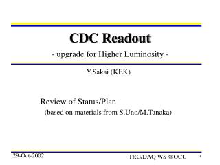
CDC readout system status MT 2009 July 7
BELLE II CDC readout electronics CDC
Prototype CDCreadout card (FY2009) • # of channels(Total:~15000) • 48~64ch/board • Amp shaper • Shaping time:~100nsec • Gain:~1V/1pC(TBD) • Dynamic range:2pC(TBD) • TDC FPGA TDC • Timing resolution:1nsec • ADC • Resolution:10bit • Sampling rate:~32MHz • L1 buffer • Depth:5usec max Test board was developed to determine above params using test chamber.
Test boardfor test(prototype readout card will be designed based on this.) • Small tube chamber (tungsten wire) • Fe55 5.9 keV X-ray • Gas(Ar90%+CH410%), P10 Gas • 1.65kV This AmpShaper was developed for other application. Modification will be done by Dr. Taniguchi. RocketIO will be tested by Dr. Igarashi Firmware design will be done by Dr.Uchida FPGA-TDC has been used for J-PARC. Ampshaper 16ch AD9212x2 RocketIO RMS=0.47ns TDC&L1 buf PCB was designed by Mr.Saito and Mr. Ikeno
Specification of Test board(detail) • Analog(Amp-shaper for DB-decay exp) • Peaking time:~50nsec OK • Pulse width:~200nsec OK • Gain : 8V/pC 1~2V/pC • Dynamic range : 2V max OK • Noise : ~2500 e @ 40pF OK • Function • ADC 10bit 32MHz • TDC 1nsec • L1 buffer : 5usec max • Two modes for data format • Waveform data readout mode • Compression mode Timing and Q BLR modification has been done These values will be confirmed by beam test
Amp shaper modification We started development of Amp-shaper for BELLEII CDC. Present Amp shaper Analog buffer BLR Amp shaper CMOS digital Bias circuit
FPGA Block diagram Trigger FADC I/F Ring buffer 5usec 500nsec window Readout FIFO Q(sum) & Data formatter SiTCP Or RocketIO I/F ADC TDC ASD Slow control DAC, ADC, Ring buffer etc
Function L1 buffer length : 5usec Max variable Window(for Q info:S) 500nsec variable ADC waveform New old Comparator output Timing data and Q or waveform data are Transferred to external interface Trigger Data format will be determined within a month
Schedule(short term) End of Aug. End of Sept. Mid of Oct. prototyping Firmware w/o rocket IO modification Uchida Preparation for beamtest Design and feedback submission Amp shaper Taniguchi, Shimazaki Test with rocket IO Nakao, Igarashi PCB design Saito, Ikeno