Download
1 / 20
200 likes | 394 Views
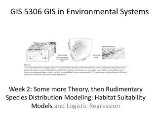
Working with GIS Maps and GIS in collaborative planning. Branislav Olah Technical University in Zvolen, Slovakia. Using maps in collaborative planning. 1. GENERAL INFORMATION ON MAPS. 2. MAP TYPES AND SOURCES. 3. USING MAPS IN CP. Using GIS in collaborative planning.

E N D
Working with GIS Maps and GIS in collaborative planning Branislav OlahTechnical University in Zvolen, Slovakia
Using maps in collaborative planning 1. GENERAL INFORMATION ON MAPS 2. MAP TYPES AND SOURCES 3. USING MAPS IN CP
Using GIS in collaborative planning 1. GENERAL INFORMATION ON GIS TECHNOLOGY 2. INTRODUCTIONTO VARIOUS GIS SOFTWARES 3. WORKING WITH ARCVIEW 4. VISUALISATION 5. MAP TABLE and MAP TALK 6. WEB GIS PAGES
1. GENERAL INFORMATION ON GIS TECHNOLOGY Basic terminology and principles Planning processes are bound with phenomenasuch as space (surface, area, territory) and time (timetable, duration of process). Since planned activities must be exactly localised and described in space (due to ownership, legal rights, state administration or affected groups) we need maps (orthogonal description of earth’s surface). Conventional maps consist of permanently visible information on topography (location of objects and hypsometry of relief) printed in a 2D form (e. g. paper). Geographical information systems (GIS) have the same basics as conventional (printed) maps, (e. g. coordinates, topography, information system) but in some aspects go beyond printed maps. They are thus virtual maps as well as software products enabling the user to change, to query, to analyse, and to create spatial data.
1. GENERAL INFORMATION ON GIS TECHNOLOGY Possibilities Profits and effectiveness Digital spatial data, though occupying rather large space on memory media (PC hard disc, CD, DVD), are very versatile, portable and universally usable. Doing work (analyses, overlays, visualisation etc.) with them is very fast and #THE# results are usable for various purposes. A user is able to choose which information he wants to be shown according to his actual needs. He could combine spatial information in a form most suitable for his purposes (partial results, analyses outcomes, public presentations).
1. GENERAL INFORMATION ON GIS TECHNOLOGY Preparing data GIS is digital software therefore it needs digital data. Newer geographical data coming from satellite images, aerial photographs or GPS (global position systems) are already digital files. Older analogue data (printed maps) have to be converted to digital form (scanned) and to be assigned coordinate attributes (georeferenced). Various software modules can be applied (e. g. TRIM in ArcView). The basic principle is that there is a concrete point on a map (at least 3 points) and 2 known coordinate values (geographical latitude and longitude) are added from the most suitable or preferred coordinate system. Thus, the whole picture (map) is allocated into the proper coordinate system.
1. GENERAL INFORMATION ON GIS TECHNOLOGY Coordinate systems All GIS spatial data are created according to basic cartographic principles (e. g. projection). However, there exist regional differences in coordinate systems of existing maps. They are a result of historical, regional, political or sectoral differences. “FOR EXAMPLE,” in the Slovak #Republic” there exist two different coordinate systems. The first one is the military system S-42 (Gauss-Kruger projection used in #ENTIRE” former Soviet block) and the second one is the former Czechoslovakia civil system, JTSK (Křovák’s projection). Both systems are widely used in GIS maps and a user must be aware of this when using data from various sources and use conversion from one to another (e. g. Samuel in ArcView). This phenomenon is even more serious when using data created in different parts of the world (e. g. UTM, WGS 84).
2. INTRODUCTIONTO VARIOUS GIS SOFWARES • IDRISI, TOPOL, KOKES, MICROSTATION, CAD, ERDAS, GRASS, LEICA, ArcGIS (ArcInfo+ArcView) • their pros and cons • their uses in various institutions • focusing on ESRI ArcView
3. WORKING WITH ARCVIEW Interface ArcView GIS interface is very user friendly. It works in the Windows #operating# system, and therefore shares all #OF# its basic principles. The first window after running the programme is Project window offering the user to move to subcategories such as Views, Tables (attributes), Charts, Layouts (visualisation) or Scripts (programming). The basic ArcView package is rather restrictive, but could be upgraded by external modules (Spatial, Network, Image, 3D analyst), or extensions (usually Scripts freeware) which enable the user to do more sophisticated analyses. Project is a type of work configuration, and opened (created) files can be saved to the hard disk and reopened later; thus, a user can continue to work exactly where he stopped. Files themselves are independent from the project and can be changed in other applications. The saved project remembers only the route to the files on the hard disk (or other memory units).
3. WORKING WITH ARCVIEW View View is a basic window used to create, change, and manage image, grid, vector and 3D data. On the top there are tool folders and direct buttons for the most frequently used tools. On the left side there is a list of opened files and the largest white part is for viewing the files. A user can use already existing files or create new files.
3. WORKING WITH ARCVIEW Image data Image data are all data in picture format files (.BMP, .JPG, .TIFF etc) with added spatial coordinates (e. g. maps, aerial othophotographs, satellite images). They are used as background information for vector or grid data.
3. WORKING WITH ARCVIEW Vector data Vector data (called shapefile in ArcView) consist of graphics and its attribute, written in the attribute table (database). Each graphic has just one row in the attribute table. Graphics are basically points, lines or polygons. Points are used to mark single points in space such as altitude (mountain peak), single buildings or settlements (depends on scale) or other single point spatial phenomena. Lines are used to describe linear features such as altitude contours, roads, rivers, borders, wire lines, pipelines etc.
3. WORKING WITH ARCVIEW Polygons represent area features such as built-up areas, forests, grasslands, croplands, water bodies, and residential or industrial areas. It is important to think ahead to which spatial phenomenon one wants to create and then analyse, since each of these vector data requires a different approach, or are supported by different GIS modules.
3. WORKING WITH ARCVIEW Grid data Grid data represent spatial phenomena interconnected mostly with surface (elevation, inclination, aspect). To create or analyse them, #A# module Spatial analyst is needed. TIN data TIN is an ArcView name for 3D data generated from grid data. They enable the user to view #THE# Earth’s surface (georelief) in 3D visualisation. To create or analyse them, #A# module 3D analyst is needed.
3. WORKING WITH ARCVIEW GIS Analysis (horizontal and vertical) vector files – overlay (clip, intersect, union, dissolve), distance, summarise, tabulate, query + database (attributes) analysis) grid files – derive slope, aspect, tabulate, query, hillshade, reclassify tin files – derive slope, aspect, tabulate, query, hillshade,3D scene
4. VISUALISATION Presenting a recent situation, or alternatives to a proposed plan during the planning process, or to the public is possible either on live GIS files or via exporting maps as pictures (JPG, TIFF or other graphic formats). These exported pictures (called layouts in ArcView) consist of basic map objects, their legend, scale bar, north orientation, etc. They can be prepared in colour (for on screen presentations – e. g. Microsoft Office Power point or a similar program), or in black and white graphics (suitable for easy printing or copying). It is important to choose a proper way of presenting outfit (usage of colours, scale, point of view etc.) so that other participants can understand it.
4. VISUALISATION 3D scene
5. MAP TABLE and MAP TALK • Examples of using Map Table in collaborative planning • presented by Mr. J. de Kroes from Wageningen University (http://www.wageningenuniversiteit.nl)
5. MAP TABLE and MAP TALK Participants expressing their views on the planning problems at the MapTable
6. WEB GIS PAGES • Examples of using GIS in collaborative planning • http://www.maptalk.nl/ (in English and Deutsch) • http://www.virtuocity.eu/helmond/ (in Dutch) • http://opus.tkk.fi/softgis/index.htm (in Finnish, intro in English) • http://www.nja.dk/serviceomraader/naturogmiljoe/natur/vilstedsoe/vilstedsoe.htm (in Danish) • http://www.wing.wur.nl/home.asp (in Dutch and English) • http://www.virtuocity.eu/helmond/main.php


![Making maps, many maps! [What is GIS?]](https://cdn1.slideserve.com/3592384/making-maps-many-maps-what-is-gis-dt.jpg)