Download
1 / 1
10 likes | 251 Views
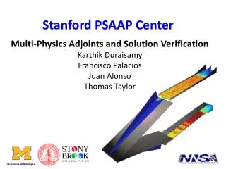
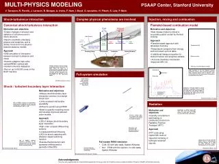
MULTI-PHYSICS MODELING PSAAP Center, Stanford University. V. Terrapon, R. Pecnik, J. Larsson, B. Morgan, A. Irvine, F. Ham, I. Boyd, G. Iaccarino, H. Pitsch, S. Lele, P. Moin . Heat Losses. Shock-turbulence interaction. Complex physical phenomena are involved.

E N D
MULTI-PHYSICS MODELING PSAAP Center, Stanford University V. Terrapon, R. Pecnik, J. Larsson, B. Morgan, A. Irvine, F. Ham, I. Boyd, G. Iaccarino, H. Pitsch, S. Lele, P. Moin Heat Losses Shock-turbulence interaction Complex physical phenomena are involved Injection, mixing and combustion Heat Losses Shock Train (M ~ 2.5) Mixing and combustion (M > 1) Canonical shock/turbulence interaction Flamelet-based combustion model Bow Shock • Motivation and objectives • Drastic changes in structure and statistics of turbulence and in shock structure • Need to elucidate underlying physics and dynamics, and to devise novel and more physics-based turbulence models • Approach • DNS simulation of interaction between isotropic turbulence and shock • Solution-adaptive high-order central/WENO method with minimal numerical dissipation • Run on up to 65,536 cores on the BG/P machine • Motivation and objectives • Heat release model is critical to accurately predict unstart by thermal choking • Approach • Flamelet-based approach with tabulated chemistry • Temperature computed from energy and not looked up from table • 3 additional transport equation for mixture fraction and progress variable • Accurate chemistry mechanism (improved GRI-3.0) Flow Mach ~8 Fuel Injection Turbulent Boundary Layer Laminar/Turbulent Boundary Layer Nozzle/Afterbody Forebody Ramp Inlet/Isolator Combustor Temperature in [K] OH mass fraction Isotropic turbulence passing through a nominally normal shock wave. The figure shows the shock as a transparent sheet and eddies colored by the vorticity magnitude. Note the increased vorticity, decreased size, and predominant alignment in the shock-plane of the post-shock eddies. Water mass fraction (progress variable) Unfueled side RANS simulation of the DLR HyShot II ground experiment: contours along combustor bottom wall, along symmetry planes and at different cross-sections. Mass flow rate of H2 injected corresponds to an equivalence ratio of ϕ=0.3. Full-system simulation inside walls Fueled side Isolator bottom wall / side wall corner, pressurecontour plot indicates induced bow shocks Work performed by J. Larsson Shock / turbulent boundary layer interaction Comparison with DLR HyShot II ground experiment: normalized pressure along the inside walls at the symmetry plane of the unfueled and fueled sides, pressure normalized by the static pressure at the isolator/combustor inlet. • Motivation and objectives • Oblique shock/boundary layer interaction common in scramjet shock train • Limits scramjet inlet/isolator operability • Difficult to predict using RANS • Need to quantify modeling errors and develop improved reduced order models. • Approach • LES of oblique shock/boundary layer interaction • High-order compact differencing scheme • Localized Artificial Diffusivity (LAD) for shock capturing with dilatation-based switching function • Rescale/Reintroduction with spanwise shifting used to generate inflow BCs Work performed by V. Terrapon Unfueled combustor LES of SWTBLI: contours of instantaneous density gradient magnitude at half span and instantaneous streamwise velocity contours near the wall (y/δ = 0.05, y+ = 24) Radiation • Motivation and objectives • Quantify uncertainty in wall heating of combustor/nozzle from Radiative Thermal Transport (RTT) • Approach • RTT code using implicit MC method • Spectral modeling of hydrogen scramjet species Mach 7.4 Comparison of Monte Carlo RTT code with Fleck and Cummings results (J. Comp. Phys. Vol. 8, 1971) for cold slab heated by a blackbody. Pressure contour plots for unfueled and fueled combustor of the Hyshot II scramjet simulation Fueled combustor H2 injectors, wall streak lines and pressure contours of scramjet combustor LES of SWTBLI: turbulent structures visualized by the second invarient of the velocity gradient tensor (Q) and colored by the streamwise vorticity • Full system RANS simulation • Cold: 3D with side walls, Spalart-Allmaras • Hot: FPVA with H2 injection, no side walls, Spalart-Allmaras Comparison of spectral code with Nelson results (J. Thermophysics and Heat Transfer, Vol. 11, 1997) for model combustor at M=14. Emitting species are H2O and OH. Pressure contour of bow shock at forebody leading edge Work performed by A. Irvine Work performed by B. Morgan Work performed by R. Pecnik and V. Terrapon Acknowledgments This work was supported by the United States Department of Energy under the Predictive Science Academic Alliance Program (PSAAP) at Stanford University