Download
1 / 20
200 likes | 311 Views
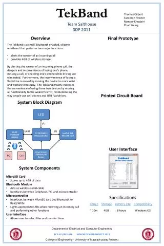
Experience the cutting-edge TekBand, a Bluetooth-enabled wristband designed for seamless phone call alerts via vibration and LED display. Our presentation covers the MDR goals, development approach, and system overview, highlighting the challenges and solutions in communication, data storage with MicroSD, and energy efficiency. With a focus on teamwork and effective communication, we've designed a prototype that is fully functional for both Bluetooth communication and data storage, all encapsulated in a robust silicone band with a strong clasp.

E N D
MDR PresentationTekBand Cameron Proctor Ramsey Khudairi Thomas Gilbert Chad Young
Overview • MDR Goals and PDR Concerns • Development Approach • System Overview • Component Implementations • CDR Goals and Final Demo • Questions
The TekBand • Bluetooth enabled wristband • Alerts wearer when receiving a phone call • Vibration • LED display • Wireless storage
MDR Goals & PDR Concerns MDR Goals: • Read/write between MicroSD and microcontroller • Select and test battery • Create and test sample band with clasp • Pair with Bluetooth module • Pair and send information to both cell phone and PC PDR Concerns: • Power constraints • Transmitting data via Bluetooth • Communicating with MicroSD card
Development Approach • Team roles • Division of work • Assisted each other when stuck and worked together • Met together regularly • Discussed, analyzed and resolved any problems • High level of communication • Email • Dropbox • Portable computers
The Band • Selected silicone-rubber & neodymium magnets • 1:1 ratio • Used to make mold and band • Strongest available magnets • Design Tasks • Make mold and test band • Test strength of material • Test clasp
Casting Mold and Band • Mold • Poured silicone-rubber around wooden “band” • Band • Applied rubber-to-rubber release to mold • Mixed and poured rubber in mold • Magnetic clasp • Weak • Waiting on larger magnets
Stress Testing • Instron Machine • Stretches material • Measures force and displacement • Stress = Force/Area • Material constant • Cross-section: 5mm x 13mm • Max stress: 0.43 Mpa • Can handle 6.4 lbs. force • Bigger band can handle more force • Hardware failure first
Bluetooth - Profiles • Serial Port Profile • Created to replace RS-232 • Transmits and receives data via UART • Most Bluetooth modules support it • Hands-free Profile • Most modern phones have it • We were able to display caller ID information onto our computer
Our Bluetooth Module • We Selected the KC-21 • UART • SPI port • High Speed of 3Mbps • Currently has the Serial Port Profile • Makes communication for wireless storage easy • We are able to power and pair with the module
Transmitting data via Bluetooth **WILL BE ADDED**
Microcontrollers • We Selected the PIC16F1827 (Microchip) • UART • 2 SPI ports • Low power • Design Tasks • Design PCB Demo Board • Solder fine pitch component • Program Microcontroller to verify PCB • Read and Write to MicroSD
PCB Demo Board Design • Need to access pins, yet too small to solder to directly • Breakout General I/O Pins • Breakout SPI and UART Pins • Provide connection for Programming • Designed using PCB Artist, ordered through Advanced Circuits • Challenge: Hand soldering fine pitch (8 mils) 28 pin UQFN package
Programming the Microcontroller • Initial Goal: Verify circuitry • Solution: simple program programm that blinks an LED • Verifies that programming circuitry is correct • Verifies I/O breakouts are correct • Blinking frequency verifies internal oscillator /* Blink LED connected to RA0 */ //PORTA = 0x00; bits_off(PORTA, 0b00000001); __delay_ms(500); //PORTA = 0x01; bits_on(PORTA, 0b00000001); __delay_ms(500);
Programming the Microcontroller (Cont.) • With PCB verified, the goal is to read and write to the MicroSD • MicroSD Read and Write Overview • All read and write operations done in 512 byte blocks as per SD spec. • First send read or write command to the MicroSD • Then transmit the block address for the SD memory • Finally send or receive 512 bytes of data • Byte transmission is handled via the SPI
Demo Program • Goal: Demonstrate reading and writing capability with MicroSD card • Write a number sequence to the MicroSD card • Store 0, 1, 2, 3, …, 15 on the MicroSD • Access the correct memory location, read number sequence and store in an array • Array now contains what was read from the card • Display contents of array sequentially in binary using 4 LEDs connected to the general purpose IO
CDR Goals & Demo Day CDR Goals: • All components fully functional (outside of band) • Completed prototype of band including clasp and display design Demo Day: • One fully functional wristband: • Can store data from PC to band via Bluetooth • Will vibrate and light up specific LED when receiving a phone call