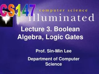
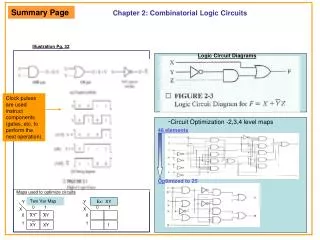
Chapter 2: Combinatorial Logic Circuits
Summary Page. Chapter 2: Combinatorial Logic Circuits. Illustration Pg. 32. Logic Circuit Diagrams. Clock pulses are used instruct components (gates, etc. to perform the next operation). - Circuit Optimization -2,3,4 level maps. 48 elements. Optimized to 25. Maps used to optimize circuits.

Chapter 2: Combinatorial Logic Circuits
E N D
Presentation Transcript
Summary Page Chapter 2: Combinatorial Logic Circuits Illustration Pg. 32 Logic Circuit Diagrams Clock pulses are used instruct components (gates, etc. to perform the next operation) -Circuit Optimization -2,3,4 level maps 48 elements Optimized to 25 Maps used to optimize circuits Two Var Map Y Y Ex: XY 0 1 0 1 X X 0 1 XY XY 0 1 XY XY 1
Combinatorial Logic CircuitsChapter 2: Digital circuits are hardware components that manipulate binary information. The circuits are implemented using transistors and interconnections in complex semiconductor circuits called integrated circuits. Each basic circuit is referred to as a logic gate. A mathematical notation that specifies the operation of each gate and can used to analyze and design circuits is called Boolean algebra. Named after George Boole. In this chapter we will discuss gates and the techniques used in designing circuits from these gates and cost effective circuits. These techniques are based on Boolean algebra. One aspect of design is to avoid unnecessary circuitry and excess cost, called optimization. Karnaugh Maps provide a graphical method for enhancing understanding of optimization and solving small optimization problems. These techniques apply to most of the generic computer , except for memory circuits RAM and cache. Binary logic deals with variables that take on two discrete values 0 and 1. And Gate Z=X Y or Z=XY X Y OR Gate Z= X + Y X Y Not Gate (or inverter) Z= X Z Z Z X X Y Z= XY 0 0 0 0 1 0 1 0 0 1 1 1 X Y Z= XY 0 0 0 0 1 1 1 0 1 1 1 1 X Z= XY 0 1 1 0
Combinatorial Logic CircuitsChapter 2: XOR Gate F= X Y + X Y = X + Y NAND Gate F=X Y X Y NOR Gate F= X + Y X Y X Y F F F X Y Z= XY 0 0 1 0 1 1 1 0 1 1 1 0 X Y Z= XY 0 0 1 0 1 0 1 0 0 1 1 0 X Y Z= XY 0 0 0 0 1 1 1 0 1 1 1 0 Pg 32
Combinatorial Logic CircuitsChapter 2: • A multiple output Boolean function is a mapping from each of the possible combinations of values 0 and 1 • F(X,Y,Z) = X + Y Z • There are two terms X and Y Z The function F is equal to 1 if ( X=1) or ( Y Z =1) • or restated The function F is equal to 1 if ( X=1)or ( Y=0 and Z=1) • A Boolean equation expresses the logical relationship between binary variables. • It is evaluated by determining the binary value of the expression for all possible combination. • A binary can be represented by a truth table. • The number of rows in a truth table is 2n where n is the number of variables in the function • X Y Z F • 0 0 0 0 • 0 0 1 1 • 0 1 0 0 • 0 1 1 0 • 0 0 1 • 1 0 1 1 • 1 0 1 • 1 1 1 1 Logic Circuit Diagram for F = X + Y Z X Y Z F Logic Circuits of this type are called combinatorial logic circuits since the variables are combined by the logical operations
Combinatorial Logic CircuitsChapter 2: • Basic Identities of Boolean algebra: ( result is either 0 or 1 ) • OR AND • X + 0 = X 2) X 1 = X (two possibilities 0 1 = 0, 1 1 = 1 • X + 1 = 1 4) X 0 = 0 • X + X = X 6) X X = X • X + X = 1 8) X X = 0 • X = X • 10) X + Y = Y + X 11) XY = YX Commutative • ( COMMUTATIVE: order there written will not affect the result for and, or ) • X +( Y + Z) = (X + Y) + Z 13) X(YZ) = (XY)Z Associative • (ASSOCIATIVE: The result of applying an operation over 3 variables is independent of the order that is taken ) • X(Y + Z) = XY + XZ 15) X + YZ = (X + Y)(X + Z) Distributive • (DISTRIBUTIVE: 15) does not hold in ordinary algebra: each variable in an identity can be replaced by a Boolean expression ) • EX: (A+B)(A+CD) Let X=A, Y=B, AND Z=CD and applying the second distributive law • (A+B)(A+CD)= A + BCD • X + Y = X Y 17) X Y = X + Y DeMorgan’s • Demorgan’s: General form: X1 +X2 + ….XN = X1 X2 ….. XN X 1 = X, X 1 = X
Combinatorial Logic CircuitsChapter 2: Algebraic Manipulation: Boolean algebra is useful for simplifying digital circuits. F = XYZ + XYZ + XZ = XY(Z + Z) + XZ Identity 14 X(Y + Z) = XY + XZ = XY 1 + XZ Identity 7 = XY + XZ Identity 2 X + X = 1 Original Circuit X 1 = X Truth Table X Y Z F 0 0 0 0 0 0 1 0 0 1 0 1 0 1 1 1 1 0 0 0 1 0 1 1 1 1 0 0 1 1 1 1 X Y Z F Optimized Circuit F = XY + XZ X Y Z F
Combinatorial Logic CircuitsChapter 2: Combinatorial Logic CircuitsChapter 2: • A product term in which all the variables appear exactly once, either complimented or uncomplemented is called a minterm. • Its characteristic is that it represents exactly one combination of the binary variables in a truth table. • It has the value 1 for that combination an 0 for all others. • There are 2n distinct minterms for n variables. In General • X Y Z Product Term • 0 0 0 X Y Z • 0 0 1 X Y Z • 0 1 0 X Y Z • 0 1 1 X Y Z • 0 0 X Y Z • 1 0 1 X Y Z • 1 0 X Y Z • 1 1 1 X Y Z Symbol Mo M1 M2 M3 M4 M5 M6 M7 Mo 1 0 0 0 0 0 0 0 M1 0 1 0 0 0 0 0 0 M2 0 0 1 0 0 0 0 0 M3 0 0 0 1 0 0 0 0 M4 0 0 0 0 1 0 0 0 M5 0 0 0 0 0 1 0 0 M6 0 0 0 0 0 0 1 0 M7 0 0 0 0 0 0 0 1
Combinatorial Logic CircuitsChapter 2: A function F can be expressed as the logical sum of the minterms: F= XYZ + XYZ + XYZ+ XYZ = Mo + M2 + M5 + M7 F(X,Y,Z)= M(0,2,5,7) (Stands for the logical sum (Boolean OR) of the minterms) Example: F=XYZ + XYZ + XYZ + XYZ X Y Z F 0 0 0 1 Mo 0 0 1 0 M1 0 1 0 1 M2 0 1 1 0 M3 1 0 0 0 M4 1 0 1 1 M5 1 1 0 0 M6 1 1 1 1 M7 X Y Z X Y Z X Y Z X Y Z
Combinatorial Logic CircuitsChapter 2: • Two level Circuit Optimization: • Although the truth table representation is unique, when expresses algebraically, the function appears in many different forms. • Boolean expressions may be simplified by algebraic manipulation, however this procedure is awkward since it lacks specific rules to predict each succeeding step, and its difficult to determine whether the simplest expression has been achieved. • By contrast the map method provides a straightforward procedure for optimizing Boolean functions up to four variables. • Maps for five and six variables can be drawn, but are more cumbersome to use. • The map is also known as a Karnaugh map or K-map. The map is a diagram of square representing one minterm of a function. Any Boolean function can be expresses as a sum of minterms. The map represents a visual diagram of all possible ways a function can be expressed in a standard form
Combinatorial Logic CircuitsChapter 2: • Two Variable Map: • There are four minterms for a Boolean function with two variables: So the two variable map has four squares one for each minterm fig (a).. • The map is redrawn in figure (b) to show the relationship between the squares and the two variables X and Y. The 0 and 1 marked on the left side designate the value of the variables Y X 0 1 Mo M1 XY XY 0 1 M2 M3 XY XY (a) (b) A function of two variables can be represented in a map marking the squares that correspond to the minterms of the function. AND OR Y Y X 0 1 X 0 1 X Y XY 0 0 0 0 1 0 1 0 0 1 1 1 X Y XY 0 0 0 0 1 1 1 0 1 1 1 1 0 1 1 1 1 1 F=X Y F=X + Y
Combinatorial Logic CircuitsChapter 2: • Three Variable Map: • There are eight minterms for three binary variables, or eight squares. • Note the numbers along the columns do not follow the binary count sequence. • The characteristic is that only one bit changes, corresponding to the Gray code previously mentioned. Y is uncomplimented YZ 00 01 11 10 X XYZ XYZ XYZ XYZ Mo M1 M3 M2 0 1 XYZ XYZ XYZ XYZ M4 M5 M7 M6 (c) (d) Z is uncomplimented In the two variable map the function XY demonstrated a function can consist of a single square in a map. But to achieve simplification we need to consider multiple squares corresponding to product terms. Any two adjacent squares placed horizontally or vertically (not diagonally) to form a rectangle corresponding to minterms that differ in only a single variable. The single variable appears complemented in one square and uncomplimented in the other.
Combinatorial Logic CircuitsChapter 2: Optimized Circuit • Simplifying a Boolean expression using a map. • Simplifying the Boolean function F(X,Y,Z) = m(2,3,4,5) • A 1 is marked in each minterm that represents the function =X Y + X Y XY YZ 00 01 11 10 Starting Expression X Mo M1 M3 M2 1 1 F=XYZ+XYZ+XYZ+XYZ 0 1 =XYZ + XYZ =XY ( Z + Z ) =XY(1)= XY XYZ XYZ 1 1 M4 M5 M7 M8 XY X Y Z X Y Z =X Y Z + X Y Z =X Y (Z + Z) =X Y (1) = XY • The next step is to explore collections of squares representing product terms to be considered for the simplified expression, called rectangles. • Rectangles are restricted to contain number of squares that are a power of 2 (1,2,4,8,…) • So our goal is to find the fewest rectangles that include all minterms marked with 1s • This will give the fewest product terms.
Combinatorial Logic CircuitsChapter 2: Two rectangles that are adjacent an form a rectangle of size 2, even though they do not touch each Other. But since they differ by one variable this operation (wrap around) is allowed. XYZ XYZ Mo+m2=XYZ + XYZ =XZ(Y + Y) =XZ YZ 00 01 11 10 X Mo M1 M3 M2 1 1 0 1 1 1 M4 M5 M7 M8 XYZ XYZ M4+M6=XYZ+ XYZ =XZ(Y + Y) =XZ Variables are allowed to wrap around Mo+M2+M4+M6=XYZ + XYZ + XYZ + XYZ =XZ(Y + Y) + XZ(Y + Y) =XZ + XZ = Z(X + X) = Z
Combinatorial Logic CircuitsChapter 2: • Three Variable maps exhibit the following characteristics:Example • One square represents a minterm of three literals XYZ • A rectangle of two squares represents a product term of two literals XYZ + XYZ • A rectangle of four squares represents a product term of one literal Z • A rectangle of eight squares encompasses the entire map and produces a function that is always equal to logic 1 Example: Reduces down to the variableX since it covers all of variable X, and is NOT X since it’s the 0 row 00 01 11 10 YZ XYZ XYZ X 1 1 1 1 0 1 1 1 Y Reduces down to Y XYZ XYZ
Combinatorial Logic CircuitsChapter 2: A four variable map has 16 terms. Evaluating the map is similar to previous examples, except the top and bottom, and sides all touch each other and can wrap around. Y YZ 00 01 11 10 WX Mo M1 M3 M2 00 01 11 10 M4 M5 M7 M8 X M12 M13 M15 M14 W M8 M9 M11 M10 Z
Combinatorial Logic CircuitsChapter 2: Four Variable Functions: -One square represents a minterm of four literals -A rectangle of two squares represents a product term of three literals A rectangle of 4 squares represents a product term of three literals A rectangle of 8 squares represents a product term of one literal A rectangle of 16 squares represent produces a product function that is always equal to logic 1
Combinatorial Logic CircuitsChapter 2: Y Y YZ 00 01 11 10 WX 1 1 1 wz 00 01 11 10 Mo M1 M3 M2 1 1 1 M4 M5 M7 M8 X Its permissible to use the same square more than once 1 1 1 xz M8 M9 M11 M10 W 1 1 M12 M13 M15 M14 Z F(W,X,Y,Z)= m(0,1,2,4,5,6,8,9,12,13,14) = Y + WZ + XZ