Download
1 / 46
570 likes | 1.12k Views
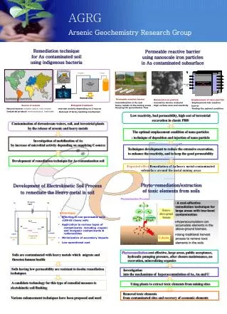
An Introduction To Permeable Reactive Barriers (PRB) Volker Birke Ernst Karl Roehl. University of Applied Sciences. University of Karlsruhe Applied Geosciences Karlsruhe. Fachhochschule Nordostniedersachsen. Definition:. Permeable Reactive Barriers are

E N D
An Introduction To Permeable Reactive Barriers (PRB) Volker Birke Ernst Karl Roehl University of Applied Sciences University of Karlsruhe Applied Geosciences Karlsruhe Fachhochschule Nordostniedersachsen
Definition: Permeable Reactive Barriers are "passive in situ treatment zones of reactive material that degrades or immobilizes contaminants as ground water flows through it. PRBs are installed as permanent, semi-permanent, or replaceable units across the flow path of a contaminant plume. Natural gradients transport cont-aminants through strategically placed treatment media. The media degrade, sorb, precipitate, or remove chlo-rinated solvents, metals, radionuclides, and other pollutants." EPA (1999), Remedial Technology Fact Sheet, 542-R-99-002
LNAPL heavy metals DNAPL contamination source GW clean groundwater plume Aquifer Aquitard reactive barrier LNAPL = light non-aqueous phase liquids DNAPL = dense non-aqueous phase liquids
PRB Concept: "Emission oriented remediation approach" Decontamination of the plume (vs. removal of the contaminant source) Passive system No active pumping of groundwater Low maintenance following installation
Basic Concept: "Emission oriented remediation approach" Clean-up of the plume, not the source Passive system: No pumping required Application: Unclear location of source(s) Slow contaminant release from source Low solubility of contaminants Large volumes of contaminated soil Built-up areas
Site Characteristics: Flow field (hydraulics) Contaminant concentrations Total contaminant mass expected Groundwater characteristics Treatability Study: Choice of attenuation mechanism and reactive material Column tests Determination of required residence time Calculation of barrier thickness
Types of reactive walls: Degradation: Chemical and/or biological reac-tions converting the contaminants to harmless by-products. Sorption: Contaminant removal from ground-water through adsorption or complexation. Precipitation: Fixation of contaminants in insoluble compounds and minerals.
Types of reactive walls: a) Continuous Barrier (CRB) b) Funnel-and-gate (F&G) system
Reactive Material Requirements • High contaminant attenuation • Good selectivity for target contaminants • Fast reaction rates • High hydraulic permeability • Long-term stability • Environmental compatibility • Sufficient availability in homogenous quality • Cost-effectiveness
Reactive Materials targeting Organic Contaminants Main source: Dahmke et al. (1996) + own additions
Reactive Materials targeting Inorganic Contaminants Main source: Dahmke et al. (1996) + own additions
PRB Operating Requirements Hydraulic conductivity: A minimum permeability must be guaranteed during barrier operation to avoid that contaminated groundwater by-passes the system. Homogeneity: In areas of favoured flow-paths there is the danger of a fast consumption of the reactive material's contaminant attenuation capability.
PRB Operating Requirements Barrier life-time: Period during which the reactive material keeps its ability to remove the target contaminants from the groundwater. Period during which the PRB keeps its hydraulic performance.
Long-term Performance Aspects The barrier life-time is governed by: • Type and concentration of contaminants • Type and kinetics of sorption and/or degradation processes. • Type and mass of reactive material • Hydraulic characteristics of the site (flow velocity) • Geochemical characteristics of the ground-water (Eh, pH, composition)
Long-term Performance Aspects Considerations on mass flux Hydraulic model of the former gas works site in Portadown, Northern Ireland. Source: Kalin, R., presentation at PRB-net Workshop, April 2001, Belfast, Northern Ireland
Long-term Performance Aspects Processes that might impair the long-term performance of PRBs: • Coatings on the particle surface of the reactive material by precipitation of secondary minerals corrosion ("rust") • Clogging of the pore space between the particles by precipitation of secondary minerals gas formation (H2) Biomass production • Consumption of the reactivity by arriving at the material's sorption capacity dissolution of the reactive material
Zero-valent Iron (Fe0) Walls granular Fe0 foamed Fe0 aggregates Organic contaminants: abiotic reductive degradation of chlorinated hydrocarbons (e.g., PCE, TCE, VC) Inorganic contaminants: abiotic reductive immobilisation of heavy metals and others (e.g., Cr, U, Mo, Tc, As, NO3). Costs: 200 - 400 €/t
Zero-valent Iron (Fe0) Walls Results of column tests conducted using commercial iron and groundwater from a contaminant plume at an industrial site. PCE dechlorination, formation of cDCE, and subsequent cDCE degradation. Source: Gillham & O'Hannesin, 1994
Zero-valent Iron (Fe0) Walls Degradation of chlorinated hydrocarbons Electron transfer from Fe0 surface (oxidation) to the chlorinated hydrocarbon (reduction, dehalogenation): 2Fe0 2Fe2+ + 4e- 3H2O 3H+ + 3OH- 2H+ + 2e- H2 X-Cl + H+ + 2e- X-H + Cl- 2Fe0 + 3H2O + X-Cl 2Fe2+ + 3OH- + H2 + X-H + Cl-
Zero-valent Iron (Fe0) Walls Uranium Molybdenum Removal of uranium and molybdenum from contaminated groundwater in porous Fe0 aggregates of a PRB system (Durango uranium mill tailings, Colorado, USA). Source: http://www.doegjpo.com/perm-barr/index.htm
Zero-valent Iron (Fe0) Walls Reductive immobilisation of heavy metals Reduction of mobile and oxidised metal compounds followed by mineral precipitation Chromium: Fe0 Fe2+ + 2e- 2H2O 2H+ + 2OH- 2H+ + 2e- H2 Fe0 Fe3+ + 3e- Cr(VI)O42- + 4H2O + 3e- Cr(III)(OH)3 + 5OH- Fe0 + Cr(VI)O42- + 4H2O Fe(III)Cr(III)(OH)6 + 2OH-
Zero-valent Iron (Fe0) Walls Coatings Coatings might block access to the reactive surfaces. Further precipitation blocks the pore spaces between some iron particles increa-sing flow velocity and decrea-sing the residence time. Source: Powell & Associates Science Services http://www.powellassociates.com/
Zero-valent Iron (Fe0) Walls Iron corrosion Anoxic: Fe0 Fe2+ + 2e- 2H2O 2H+ + 2OH- 2H+ + 2e- H2 Fe0 + 2H2O Fe2+ + H2 + 2OH- Oxic: Fe0 Fe2+ + 2e- H2O H+ + OH- ½O2 + 2e- O2- Fe0 + H2O + ½O2 Fe2+ + 2OH-
Zero-valent Iron (Fe0) Walls Precipitation of secondary minerals Carbonates HCO3- + OH- CO32-+ H2O Fe2+ + CO32- FeCO3 (s) Ca2+ + CO32- CaCO3 (s) Iron minerals Fe2+ + 2OH- Fe(OH)2 (s) 3Fe(OH)2 (s) Fe3O4 (s) + 2H2O + H2 Siderite Calcite Magnetite
Zero-valent Iron (Fe0) Walls Iron geochemistry • Stability fields for the system Fe-CO2-H2O with the following solid phases: • Am. iron hydroxide Fe(OH)3 • Siderite FeCO3 • Iron hydroxide Fe(OH)2 • Zero-valent iron Fe • (25°C, Fetotal = 10-5 M, Ctotal = 10-3 M, from: Stumm & Morgan 1996).
Zero-valent Iron (Fe0) Walls Clogging Carbonate, Ca and Fe concentration in ground-water passing through a Fe0 wall. Obvious precipitation of calcite and siderite, especially in the upstream pea gravel (Denver Federal Center, Denver, USA). Source: McMahon, P.B., Dennehy, K.F. & Sandstrom, M.W. (1999), Ground Water, 37, 396-404.
Zero-valent Iron (Fe0) Walls Carbonate precipitation Carbonate concentrations in the zero-valent iron filling of a Fe0 wall (industrial site contaminated by chlorinated hydrocarbons, New York, USA). Source: Vogan, J.L. et al. (2000), J. Haz. Mat., 68, 97-108.
Zero-valent Iron (Fe0) Walls Silicon dioxide Distribution of dissolved silicon dioxide in a Fe0 wall (Moffett Naval Station, Mountain View, CA). Source: Gavaskar et al. (2000)
Zero-valent Iron (Fe0) Walls Consumption Dissolved iron with pH in Fe0 column experiments (ZVI): Clear dissolution of iron, but only relevant at pH values < 7. Source: U.S. Department of Energy Grand Junction Office (GJO) http://www.doegjpo.com/perm-barr/
Zero-valent Iron (Fe0) Walls Groundwater constituents • Decrease of concentration in the wall: Ca, Mg, Si, bicarbonate, sulphate, H+ • Showing some influence on the reaction kinetics (corrosion, dehalogenation): Bicarbonate, sulphate, nitrate, phosphate, chloride, dissolved oxygen
Zero-valent Iron (Fe0) Walls Mass balancing Precipitation in a Fe0 wall, Copenhagen, Denmark (Kiilerich et al., 2000): 13,3 kg iron hydroxides, 2,7 kg CaCO3, 2,7 kg FeCO3 and 0,8 kg FeS per 1000 kg iron filling per year Loss of porosity in a Fe0 wall, Denver Federal Center, Denver, USA (McMahon et al., 1999): 0,35 % of total porosity per year (calculated only for the assumed precipitation of calcite and siderite)
Activated Carbon • Activated carbon: • Adsorption of organic contaminants • Specific surface: approx. 1000 m2/g • Granular • Reaction kinetics:Diffusion controlled • Critical parameter: contact time!
Activated Carbon Retardation: Retardation factor: f(c) = adsorption isotherm (linear, Freundlich, Langmuir) va = groundwater flow velocity vS = contaminant transport velocity PAH: R > 3000 (Schad & Grathwohl, 1998) Trichloroethene: R 5000 - 20000 Chlorobenzene: R 10000 - 20000 (Köber et al., 2001)
Activated Carbon Maximum barrier life-time estimation: d = reactive wall thickness va = groundwater flow velocity R = retardation factor Horizontal flow through an activated carbon reactor of 1,8 m diameter with a flow velocity of 0,5 m/d and a retardation factor of R = 3000: maximum life-time = 30 years
Activated Carbon Factors influencing barrier life-time: • Groundwater composition • Competition effects: Natural groundwater constituents and contaminants compete for the adsorption sites • Precipitation of secondary minerals: Coatings block the access to the particle surfaces and alter the reaction kinetics • Formation of biomass • Negative effect: clogging of the free pore space • Positive effect: biological degradation of sorbed contaminants possible
Monitoring Targets: Validation of Performance Longevity
Monitoring Longevity: • Checking of hydraulics • Checking groundwater chemistry Hydrochemical parameters: pH, electr. conductivity cations: Ca2+, Mg2+, Fet, anions: HCO3-, SO42-, Cl-, PO42-, NO3- • Investigation of the reactive material Coring: carbonate, XRD, REM
Current Research Focus of current R&D: • Selection of appropriate materials and processes for selective and efficient removal of groundwater pollutants. • Evaluation of longevity and long-term performance; development of models. • Upscaling – applicability and transfer of lab-scale results into the field • Hydraulics of PRBs.
Current Research: Tri-Agency-Initiative Tri-Agency Initiative, USA:
Current R&D „Reaktionswände und -barrieren im Netz-werkverbund“ („RUBIN“), BMBF, Germany • PRB projects co-operating in a network (RUBIN) • Launched May 2000, 3 years • Financial means: ca. 4 Mill. Euro. • Coordination: University of Applied Sciences (Prof. H. Burmeier, Dr. V. Birke, Dipl.-Ing. D. Rosenau) • 11 projects • 8 projects dealing with design, erection and operation of pilot- or full-scale PRBs in Germany and/or important general preparatory R&D work • 3 projects addressing general issues and missions.
Conclusions PRB long-term behaviour is a function of the deployed reactive material. PRB longevity is influenced by the pollutants to be treated and the groundwater ingredients, i.e., groundwater chemistry. The main groundwater components reveal a specific, important influence predominantly due to their higher concentrations compared to the pollutant´s concentrations. Surface reactions at the reactive material cause significant changes in geochemical conditions (pH, Eh) regarding pore space that is passed by groundwater and therefore hydrochemical changes in the composition of the groundwater.
Conclusions Mineral formation (coatings), alteration of surfaces, gas evolution and biomass can influence reactivity and permeability of a PRB. Alteration of surfaces and mineral formation can be mostly observed directly upgradient of a PRB. However, only pertaining to a few cases, detrimental effects regarding efficiency of the PRB have been observed so far. Geochemical processes are predominantly well-known and well understood. However, quantitative approaches for long-term behaviour/performance are still lacking. Current R&D projects address these issues.