Download
1 / 29
290 likes | 374 Views
The TAMDEF-I Project focused on testing leading models for ice sheet change and tectonism in South Victoria Land. Advanced GPS surveys were conducted to monitor rock motion using different spatial scales. The project aimed to discriminate signals from glacial rebound, tectonic, and volcanic activities. Site selection and field methodologies were meticulously planned for high-accuracy measurements. Robust data collection techniques were employed using GPS equipment and footprint arrays, ensuring stable monument reference points. The continuous monitoring of stations like Cape Roberts and meticulous field procedures were key to the project's success. Future phases like TAMDEF-II were planned for further study advancement.

E N D
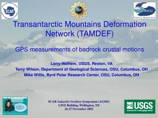
TAMDEF-I Project (TransAntarctic Mountains Deformation Monitoring Network) L. Hothem (1) and M. Willis (1,2) (1) U.S. Geological Survey (2) Byrd Polar Research Center, Ohio State University Antarctic Geodesy Symposium, AGS’01, Saint Petersburg, Russia, 18-20 July 2001
South Victoria Land TransAntarctic Mountains DEFormation Monitoring (TAMDEF-I) project
In November 1996, the Byrd Polar Research Center/Ohio State University, jointly with the US Geological Survey, began work on establishing a network of about 30 stations located at sites in the South Victoria Land region of the Transantarctic Mountains. The 4th and last in series of GPS observing campaigns for this phase of the studies was completed in the December 1999-January 2000 field season. High quality data were obtained in each of the 4 observing campaigns. Objective: test predictions of leading models for ice sheet change and tectonism
Transantarctic Mountains Deformation Monitoring Project (TAMDEF)South Victoria Land • Cooperative project - Ohio State University and USGS • Three GPS observing campaigns completed • 1996-97, 97-98, 98-99, and 99-00 field seasons • Objective: test predictions of leading models for ice sheet change and tectonism • Other geodetic measurements: • International GPS Service (IGS) stations in and near Antarctica • Absolute gravity • Tide gages
Transantarctic Mountains Deformation Monitoring Project (TAMDEF)South Victoria Land • TAMDEF-I -- Four GPS Observing Campaigns • 1-year intervals • Field seasons: 1996-97, 97-98, 98-99, and 99-2000 • Measure rock motion - 3-dimensional • Expected signals are: 1. Glacial rebound 2. Tectonic 3. Volcanic • Directions and patterns of these motions mostly distinct • GPS measurements designed to discriminate among them • Test predictions of leading models for ice sheet change and tectonism • Long-term project • TAMDEF-II is planned
GPS surveys formed geometrical elements generally at three spatial scales • Long baselines (100 to 400 km) that span the features most expected to show motion. Simultaneous tracking time is at least 2 days, often 7 days. • Station at Cape Roberts (ROB0) occupied continuously during each of the 4 observing campaigns. • Some other stations with continuous data sets spanning periods of up to 15 days. • Short baselines (10 to 25 km) crossing suspected fault zones. Simultaneous tracking time 2 to 24 hours. • Very short baselines (0.05 to 0.20 km) at each site (footprint array) to test for local motion due to such processes as frost action. Simultaneous tracking time is generally 60 minutes.
BTL MCM4 ERR ARR ROB TAMDEF Station Local fault surveys Other GPS Reference Stations Absolute Gravity Station
To obtain high accuracy or mm-level GPS measurements where biases are adequately modeled or minimized and which are free of blunders due to human error, requires careful planning and successful execution of the field methodologies employed.
Field Procedures (1) Special pins set in rock outcrop (2) Established a set of reference points, “footprint” array, at each site to monitor stability of the primary monument (3) Used specially designed “fixed-height” level mounts to ensure at a high confidence level, sub-mm repeatability for the relationship of antenna reference point (ARP) to the monument reference point (4) Employed late model GPS receivers with Dorne Margolin model choke ring antennas (5) Collected multiple-day 24-hour data sets simultaneously at 8 to 12 stations
TAMDEF Monuments Nylon cap to protect threads Plastic marker stamped with 4-character station name Threaded stainless steel 20-cm rod glued into hole drilled in bedrock
Special “Fixed-Height” Level Mount forTAMDEF Monuments ARP At each station of the TAMDEF network, relationship of Antenna Reference Point (ARP) to station mark (bottom of divot for stainless steel pin) is repeatable for each setup at the sub-mm level. Station ARR0 located adjacent to IGS station MCM4.
Arrival Heights (ARR)TAMDEF Network IGS Station MCM4 TAMDEF Station ARR0
IGS Station - “MCM4” McMurdo Station - Operational since January 1994 MCM4 with raydome cover MCM4 ARR0
GPS Equipment Receiver Models Ashtech Z12 Trimble SSE and SSi Antenna Models Ashtech & Trimble Dorne Margolin Choke Rings
Cape Roberts Tide Station (Installed 1991) co-located with TAMDEF Station ROB0 (Established November 1996) Install permanent GPS/GLONASS observing station during 2000-2001 field season
Bettle Peak (BTL) Footprint array
TAMDEF Station “ERE” Mount Erebus, Antarctica
Reliable Power Supply Essential for Continuous Data Collection Transport Case and Site storage for GPS receiver and two 40 amp-hour gel-cell batteries 30-watt solar panel generating system
Details on Field Procedures • Sites selected with relatively clear horizon • No obstructions above 10 • Minimal obstructions above 5 • Mask angle for data collection = 5 • Data collection sampling rate: • Daily (24-hour) data sets = 30-sec or 15-sec • Footprint surveys = 5-sec • Data management • All “raw” data translated into RINEX format • Categorized by station location and day of operation • Compressed and stored on CD-ROMs • Documentation for site and each occupation • Description of geology at each site • Satellite sky view • Model and serial numbers of GPS equipment used • Duration of site occupation
Quality Analysis & Data Processing • Data quality analysis • TEQC Toolkit by UNAVCO • 24-hour data sets • “Precise point positions” computed by use of JPL/NASA’s automated GIPSY-OASIS II package • “Differential positions” computed by use of National Geodetic Survey/NOAA’s PAGES package • All processed using IGS orbital coordinate data • Footprint array surveys • Software packages used include • GPSurvey V2.3 • Ashtech GPPS • Magellan AOS
SUMMARY • Methodology employed for TAMDEF GPS observing campaigns was successful overall in meeting goals for: • data free of errors due to blunders • minimizing multipath effects • multiple-day data sets relatively free of gaps