Download
1 / 33
360 likes | 598 Views
Magnetic design of a superconducting magnet for the FFAG accelerator. T.Obana , T.Ogitsu A ,T.Nakamoto A ,K.Sasaki A A.Yamamoto A , M.Yoshimoto A , Y.Mori A ,T.Origasa B The Graduate University for Advanced Studies High Energy Accelerator Research Organization A Toshiba Corporation B.

E N D
Magnetic design of a superconducting magnet for the FFAG accelerator T.Obana, T.OgitsuA ,T.NakamotoA ,K.SasakiA A.YamamotoA , M.YoshimotoA, Y.MoriA ,T.OrigasaB The Graduate University for Advanced Studies High Energy Accelerator Research OrganizationA Toshiba CorporationB
Contents • Background & Purpose • How to generate FFAG field • 2D &3D Calculation Results • Conclusion
Cancer therapy Background Downsizing the FFAG accelerator is essential so that the FFAG can be widely used. High energy physics Electric power High magnetic field is required. FFAGfield is constant. Superconducting magnet is proposed for FFAG accelerator.
Purpose The purpose of this study is to develop thesuperconducting magnetof the FFAG accelerator. 150MeVFFAG Conventional magnet of 150MeV FFAG accelerator at KEK
Magnetic Field for FFAG r : Distance from the accelerator center [m] R0 : Distance between the accelerator center and the magnet center [m] Bo : Magnetic field at the magnet center [T] K : K value ( Geometrical field index) Beam tube 0 Beam area Center of the accelerator Center of the magnet
How to generate the FFAG Field! Sextu-pole Di-pole Quadru-pole Realize FFAG magnetic field with mutipole combination!
Y – + X Y Y – – + X – + + + X + – – Current distribution Up to n=8 I=I0cos(nθ) n=1 n=2 n=3 Multi layer coil It’s too difficult to make a multi layer coil !
Y – + X Y Y – – + X – + + + X + – – Y – + Y X X – + Current distribution n=1 Simplify! n=2 n=3 With single layer Left-Right asymmetry Up to n=8 Downsize! Left-Right asymmetry & Ellipse
Y + - X – + FFAG for cancer therapy Cross-Section Current distribution FFAG LowEnergy Beam FFAG for cancer therapy HighEnergyBeam Coil parameters of FFAG for cancer therapy Excursion Coil
K value Field distribution Excursion Excursion K value & Field distributionon mid-plane@ 2D K value By/By@x=0m Local K is used to evaluate K value. Positions of the conductor can be optimized in 2D!
Y Z-Y plane Y Z Z X Straight section Y Z-Y plane Z Single winding@3D coil In single winding, one coil makes one layer. Superconducting wire Superconducting wire Y Z X Straight section
Y Z Y Z Single winding@3D coil Demerit Merit Straight length is samein each turn with 2 layers. Coil end is large. Y Z-Y plane 2 layers with 2 coils Z X Y Z-Y plane Z X
Z-Y plane Y Z Straight section Y Z-Y plane Z Straight section Twin winding@3D coil In twin winding, two coils make one layer. Superconducting wire Y Z Z Y X X Superconducting wire Z X X
Y Z Y Z Twin winding@2D coil Merit Demerit Straight length is different in each turn. Coil end is small. Y Z-Y plane 1 layer with 2 coils Z X Y Z-Y plane Z X
Top view Center of FFAG Trajectory θ X=0 m 10.0° 5.8° Coil 0° Field distribution on mid-plane@3D By/By@x=0m Z-X plane Single Winding Twin Winding X X Coil end Coil end Z Z
K value @ 3D-Result θ= 0° K value Z-X plane Top view X[m] Single Winding Twin Winding Center of FFAG Coil end Coil end Z Z X=0 m θ 5.8° X Coil 0° X
Top view Center of FFAG X=0 m θ 5.8° 2° 0° Coil K value @ 3D-Result θ= 2° K value Z-X plane Twin winding Single winding Coil end Coil end Z Z X X
Top view Center of FFAG X=0 m θ 5.8° 4° 0° Coil K value @ 3D-Result θ= 4° K value Z-X plane Single winding Twin winding Coil end Coil end Z Z X X
10.0° 5.8° BL= 0° Center of FFAG Coil X=0.0m K+1 value by BL @3D-Result K+1 value
Conclusion • 2D & 3D FFAG magnetic fields are calculated. • The optimizing program of the conductor position in 2D is developed. • Two types of 3D coil configuration are compared in terms of K value & BL. Future plan • Tracking will be done with 3D magnetic filed. • Prototype of single winding coil will be made • from this October .
What’s FFAG accelerator ? FFAG 〔Fixed Field Alternating Gradient 〕 accelerator Properties ... • Strong focusing in horizontal and verticalSynchrotron • Constant magnetic field strength in timeCyclotron Can beHigh repetition & High Intensity!
Why’s SC magnet required? High magnetic field can be generated by SC magnet. • Normal Conducting Magnets • Low Current Density < 10 A/mm2 • Field by Iron Pole • Iron Saturation 2 Tesla • Superconducting Magnets • High Current Density < 500 A/mm2 • Field by Current • Tevatron 4.5 Tesla • LHC 8.4 Tesla Accelerator size can be downsized !
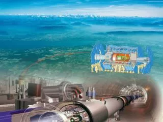
FFAG Accelerator Driven System (ADS) neutron Proton Target (Uranium) Reactor Core
Winding Technique Direct Winding Superconducting wire can adhere directly to the base. Referencehttp://www.bnl.gov/magnets/BioMed/BioMed.asp
Superconducting wire Nb-Ti Cu 1.0 mm
How to evaluate K value Total field Local field
Y Z Y Z Y Z Straight length with 2 layers Twin winding First Straight length with 2layers Z-Y plane Second Y Z-Y plane Z Single winding Straight length with 2layers First Z-Y plane Second Z-Y plane
θ Y 0° -90° 90° X Expansion plane Twin winding 180° (90°) θ -180° 0° -90° 90° (-90°) Single winding
θ How to evaluate K+1 value BL= θ=0° r Center of accelerator Coil X=0.0m
X X-Z plane Z K value & K+1 value by BL Beam traveling direction K value Local evaluation of the field B K+1 value by BL Totalevaluation of the field Z
Current S S 180° S angle S S S How to optimize the positions of the conductor 1.Evaluate the current distribution 2.Divide the area so as to be same
K+1 value X[m] Howto adjust the target! Adjust target! Calculation Calculation K+1 value Difference Target Target X[m] Adjust the 2D target so that K+1 can reach 3D target