Download
1 / 19
190 likes | 396 Views
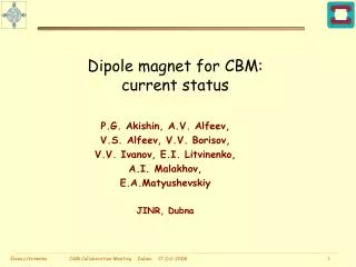
Superconducting dipole magnet for CBM. The status of the SC dipole magnet for project CBM. E.A. Matyushevskiy, P.G. Akishin, A.V. Alfeev, V.S. Alfeev, V.V. Borisov, V.V. Ivanov, E.I. Litvinenko, A.I. Malakhov.

E N D
Superconducting dipole magnet for CBM. The status of the SCdipole magnet for project CBM. E.A. Matyushevskiy, P.G. Akishin, A.V. Alfeev, V.S. Alfeev, V.V. Borisov, V.V. Ivanov, E.I. Litvinenko, A.I. Malakhov. Authors present engineering project of superconducting dipole magnet for СBMexperiment. Parameters of the magnet corresponds to last requirements of project CBMto magnetic system on formation of the working aperture and sizes of a field in a gap of the magnet and minimal field in area RICH. Split, Croatia 09.10.2009 y.
Geometrical parameters of the SC dipole magnet is shown.Aperture 1.3x1.3 m (The reserved energy into the magnet at a working current makes 3.4 MJ) 14th Colloboration Meeting, Oktober 6-9, 2009, Split, Croatia
SC dipole magnet with the aperture 1.3x1.3 m to of the magnet’s gap and length along a beam equal 1 m is shown. 14th Colloboration Meeting, Oktober 6-9, 2009, Split, Croatia
Top and down cryostats of the superconducting coils excitation of the dipole magnet is shown. Cross-section of the coil 14th Colloboration Meeting, Oktober 6-9, 2009, Split, Croatia
The block from external and internal screens with elements of installation and fastening to an yoke of the magnet is shown. 14th Colloboration Meeting, Oktober 6-9, 2009, Split, Croatia
Distributions of a field in cross-section of the magnet are shown. The left picture is for the magnet with screens andthe right picture is for the magnet without screens. 14th Colloboration Meeting, Oktober 6-9, 2009, Split, Croatia
Distribution lBl inside a gap of the magnet along a beam and of the field along the beam on distance from 1.6 m up to 4.0 m from a target is shown. /code ANSYS//code TOSCA/ 14th Colloboration Meeting, Oktober 6-9, 2009, Split, Croatia
Distribution of a field in the magnet’s gap and an integral value of the field on distance from -1.0 m up to 5.0 m along a beam from a target is shown. /code TOSCA/ 14th Colloboration Meeting, Oktober 6-9, 2009, Split, Croatia
Distribution |Bxy| of a field inside of volume (region of photo detectors of the RICH) and distribution in the form of surfaces of equal intensity of thefield are shown./code ANSYS/ 14th Colloboration Meeting, Oktober 6-9, 2009, Split, Croatia
Distributions of a field along axis of the magnet are shown. Distance “Z” change from -100 cm up to 200 cm. The left picture is for the magnet with screens andthe right picture is the magnet without screens. 14th Colloboration Meeting, Oktober 6-9, 2009, Split, Croatia
Distributions of a field in a plane (Х-Y) with coordinates X (0, 1.6) m Y (0.5, 1.5) m on distance of 1.6 m and 1.7 m from a target accordingly (the region of photo detectors) are shown. /code RADIA/. 14th Colloboration Meeting, Oktober 6-9, 2009, Split, Croatia
Distributions of a field in a plane Х with coordinates X (0, 1.6); Y (0.5 m, 1.5) on distance of 1.8 m and 1.9 m from a target accordingly (the region of photo detectors) are shown. /code RADIA/ 14th Colloboration Meeting, Oktober 6-9, 2009, Split, Croatia
Distributions of the field in a plane (Х-Y) on distance of 1.8 m from a target (the region RICH) are shown. with screens without skreens 14th Colloboration Meeting, Oktober 6-9, 2009, Split, Croatia
The considered variant design of the magnet well answers tasks in view on size of working aperture of the magnet and acceptable values of a field in the region of photo detectors RICH. The big ponderomotive forces influence on coils. In of a magnet's gap in a horizontal plane these forces make approximately 86 tons on meter of length with a gap 5.2 sm. There is a problem of creation of coils with necessarypower characteristics. To create system of support hold such efforts and to provide a thermal flow for through them no more than 0.3 W on meter of length of the coil is practically impossible. • We should or increase the charge of liquid helium and nitrogen (bearers of a cold) or so to change a design of the coil in order the coilperceived these efforts without big thermal losses. • Possible variant of a design of a winding with increased distance up to iron ofthe yoke and by support of labyrinth type is shown on following slides. 14th Colloboration Meeting, Oktober 6-9, 2009, Split, Croatia
Pondermotiveforces near 43 t on meter of length operate on a winding in a direction tothe yoke. Forces are perceiving by support and a rigid casing of the coil. The support is executed of plastic with application Kevlarthat allows to lower a thermal flow to helium volume of the coil up to 0.08 W along one support. The common thermal flow to Helium vessel through 36 support makes 2.88 W. Reduction of a thermal stream through radiation is reached by application of the nitric screen and super insulation. The external vacuum casing is executed from stainless steel with thickness of walls 10 mm. It allows to provide the minimal deflection of wallswhen pumpinginternal volume and take efforts from support of the coil. Cross-section of a windings excitation through a support is shown. 14th Colloboration Meeting, Oktober 6-9, 2009, Split, Croatia
Cryostatsof a windings excitation of the dipole magnet with support of the coil is shown. 14th Colloboration Meeting, Oktober 6-9, 2009, Split, Croatia
SC dipole magnet with the aperture 1.3x1.37 m (1.87 m between racks) and length equal 1 m along a beam is shown.(Energy reserved in the magnet at a working current into a winding makes 3.9 MJ) 14th Colloboration Meeting, Oktober 6-9, 2009, Split, Croatia
Conclusion • The contemplated variant of the engineering design for the magnet with a gap 1.3х1.6х1.0 m (height, width and length) and aperture 1.3x1.3 m provides a required magnitude of the field inside the gap and good screening of the field within RICH • The factor of screening of the magnetic field in comparison with the variant without screens is close to 3.5-4 times. A drawback of the proposed screens is their big metal consumption. It is necessary to determine an optimal form and sizes of the screens to increase screening factor and to reduce their metal consumption. • The gap of the magnet satisfies the available geometry of the STS detector and has no elements which could interfere with moving the detector in the gap and directly in front of the magnet. • The increase of sizes of a magnet in connection with necessity of accommodation STSinto a gap increase capacity of materials at manufacturing of a magnet. Cost of manufacturing of a magnet grows as a result of it. • The increase of sizes of aperture increase current at the coil and increase forces which influence this coil. It is necessary so to change a design of box of the coil’s that it could perceive operating efforts. 14th Colloboration Meeting, Oktober 6-9, 2009, Split, Croatia
Thanks for your attention! 14th Colloboration Meeting, Oktober 6-9, 2009, Split, Croatia