Download
1 / 26
260 likes | 497 Views
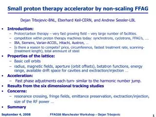
Accelerator Design for FFAG-KUCA ADSR. Y.Ishi Mitsubishi Electric Corp. July 7 2003. What is ADSR?. Accelerator Driven Subcritical Reactor. charged particle. target for generating neutron. accelerator. subcritical reactor. Beam off chain reaction stops Safer system !.

E N D
Accelerator Design for FFAG-KUCAADSR Y.Ishi Mitsubishi Electric Corp. July 7 2003
What is ADSR? Accelerator Driven Subcritical Reactor charged particle target for generating neutron accelerator subcritical reactor Beam off chain reaction stops Safer system !
FFAG for ADSR Accelerators should have high power efficiency Pbeam / Ploss > 30% FFAG • Fixed field -extremely high rep. rate(1kHz) high intensity -superconducting magnet small Ploss • Alternating gradient -compact size
ADSR in Kyoto University Research Reactor Institute(KURRI) Feasibility study of ADSR Five-year program 2002 – 2006 Subject • Accelerator technology -variable energy FFAG • Reactor technology -basic experiments for energy dependence of the reactor physics
basic experiments future upgrade Beam specifications H+ 20-150MeV 1mA 120Hz H+ 200MeV 100mA 1kHz Beam species Energy Average beam current Rep. rate
FFAG – KUCA ADSR system schematic diagram 100keV 2.5MeV 20MeV 150MeV ion source injector booster KUCA subcritical reactor main ring
Parameters of the Accelerator Complex Einj Eext Lattice type Acc. scheme # of cells k value coil/pole Pext/Pinj Rinj Rext Injector 100keV 2.5MeV Spiral Induction 8 2.5 coil 5.00 0.60m 0.99m Booster 2.5MeV 20MeV Radial DFD rf 8 4.5 coil 2.84 1.42m 1.71m Main ring 20MeV 150MeV Radial DFD rf 12 7.6 pole 2.83 4.54m 5.12m
Beam intensity schedule Scheme continuous continuous 12-turn 1-turn 1-turn 1-turn Efficiency 90% 70% 80% 95% 95% 95% pulse length 50ms 5ms 5ms 50ns 50ns 65ns peak current 5mA - 32mA - 2.4A - 1.6A Ion source Injector inj. Injector ext. Booster inj. Booster ext. Main ring inj. Main ring ext. <I>=1.6A ×65ns ×1kHz = 108mA
Space charge effects in the injector Dnx=0.05, Dny=0.16 when ex=50pmm-mrad ey=100pmm-mrad
Pulse structure of the beam Vgap=2kV continuous injection to the injector Vgap=30kV compressed pulse from the injector
Acceleration voltage pattern spill acc. period 5ms injection 50ms acc. Voltage
Specifications of the booster extraction 20 0.6496 1.650 1.774 5.564 1.487/1.487 injection 2.5 0.2286 1.346 1.467 2.412 0.633/0.633 T(MeV) Br(Tm) k Vrf(kV) Rmin(m) Rmax(m) frev(MHz) BF/FD tune 4.5 3(10) (3.24,1.56)
Variable energy • Extraction energy of the injector is fixed at 2.5MeV • Momentum ratio in the main ring is fixed at 2.81 • Need to vary k value in the booster k T(MeV) T(MeV) booster main ring 0.5 3.0 23 4.5 20 150
Flat-pole multi-coil B=B0(r/r0)k
Specifications of the main ring (the same design as KEK 150MeV) extraction 150 1.8390 5.023 5.229 4.651 1.699/0.998 injection 20 0.6496 4.451 4.633 2.106 0.678/0.398 T(MeV) Br(Tm) k Rmin(m) Rmax(m) frev(MHz) BF/FD tune 7.6 (3.73,1.55)
Injector Layout Booster Main ring