Download
1 / 39
400 likes | 643 Views
Accelerator Design and Construction for FFAG-KUCA ADSR. Y.Ishi Mitsubishi Electric Corp. Oct. 15 2004. ADSR. Accelerator Driven Subcritical Reactor. charged particle. target for generating neutron. accelerator. subcritical reactor. Beam off chain reaction stops Safer system !.

E N D
Accelerator Design andConstruction for FFAG-KUCAADSR Y.Ishi Mitsubishi Electric Corp. Oct. 15 2004
ADSR Accelerator Driven Subcritical Reactor charged particle target for generating neutron accelerator subcritical reactor Beam off chain reaction stops Safer system !
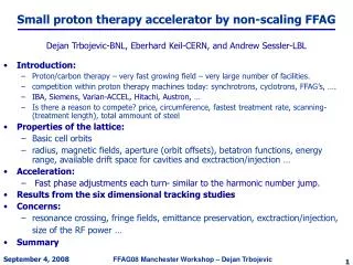
FFAG for ADSR Accelerators should have high power efficiency Pbeam / Ploss > 30% FFAG (B~rk) • Fixed field -extremely high rep. rate(1kHz) high intensity -superconducting magnet small Ploss • Alternating gradient -compact size
ADSR in Kyoto University Research Reactor Institute(KURRI) Feasibility study of ADSR Five-year program 2002 – 2006 Subject • Accelerator technology -variable energy FFAG • Reactor technology -basic experiments for energy dependence of the reactor physics ( need ~10nA)
basic experiments future upgrade Beam specifications H+ 150MeV 1mA 120Hz H+ 200MeV 100mA 1kHz Beam species Energy Average beam current Rep. rate
FFAG – KUCA ADSR system schematic diagram 100keV 2.5MeV 20MeV 150MeV ion source injector KUCA subcritical reactor booster main ring
Parameters of the Accelerator Complex Einj Eext Lattice type Acc. scheme # of cells k value coil/pole Pext/Pinj Rinj Rext Injector 100keV 2.5MeV Spiral Induction 8 2.5 coil 5.00 0.60m 0.99m Booster 2.5MeV 20MeV Radial DFD rf 8 2.5 pole 2.84 1.27m 1.87m Main ring 20MeV 150MeV Radial DFD rf 12 7.5 pole 2.83 4.54m 5.12m
Beam intensity schedule Scheme continuous continuous 12-turn 1-turn 1-turn 1-turn Efficiency 90% 70% 80% 95% 95% 95% pulse length 50ms 5ms 5ms 50ns 50ns 65ns peak current 5mA - 32mA - 2.4A - 1.6A Ion source Injector inj. Injector ext. Booster inj. Booster ext. Main ring inj. Main ring ext. <I>=1.6A ×65ns ×1kHz = 108mA
Induction acceleration V=dF/dt Duty=(tb-ta)/ts =x(1-Vta/DBS) V=DBS/tb x=tb/ts High duty x large DB →large S →large
Pulse structure of the beam Vgap=2kV continuous injection to the injector Vgap=30kV compressed pulse from the injector
Acceleration voltage pattern spill acc. period 5ms injection 50ms acc. Voltage
Booster layout Rf cavity Extraction kicker magnet Injection bump magnet Injection bump magnet Injection bump magnet Injection septum electrode Injection septum magnet
Specifications of the booster extraction 20 0.6496 1.736 1.865 5.294 1.376/0.462 injection 2.5 0.2286 1.270 1.364 2.595 0.637/0.204 T(MeV) Br(Tm) k Vrf(kV) Rmin(m) Rmax(m) frev(MHz) BF/FD(T) tune 2.5 1.6 – 3.0 (2.15,1.38)
Specifications of the main ring (the same design as KEK 150MeV) extraction 150 1.8390 5.023 5.229 4.651 1.699/0.998 injection 20 0.6496 4.451 4.633 2.106 0.678/0.398 T(MeV) Br(Tm) k Rmin(m) Rmax(m) frev(MHz) BF/FD tune 7.6 (3.73,1.55)
Summary • Accelerator complex is now under construction • First beam from FFAG will be injected to subcritical reactor in 2005.