Download
1 / 19
190 likes | 261 Views
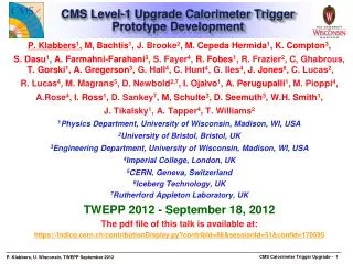
Level-1 Regional Calorimeter System for CMS. P. Chumney, S. Dasu, M. Jaworski, J. Lackey, P. Robl, W.H.Smith Physics Department, University of Wisconsin, Madison, WI, USA CHEP March 2003 The pdf file of this talk is available at: http://cmsdoc.cern.ch/~pamc/CHEP03.pdf

E N D
Level-1 Regional Calorimeter System for CMS • P. Chumney, S. Dasu, M. Jaworski, J. Lackey, P. Robl, W.H.Smith Physics Department, University of Wisconsin,Madison, WI, USA • CHEP • March 2003 • The pdf file of this talk is available at: • http://cmsdoc.cern.ch/~pamc/CHEP03.pdf • See also CMS Level 1 Trigger Home page at • http://cmsdoc.cern.ch/ftp/afscms/TRIDAS/html/level1.html
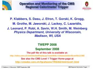
Detector Frontend Level-1 Trigger Readout Systems Event Run Builder Networks Manager Control Filter Systems Computing Services Trigger & DAQ Systems • Level-1 Trigger Requirements: • Input: 109 events/sec at 40 MHz at full Luminosity of 1034 cm-2s-1 • Output: 100 kHz (50 kHz for initial running) • Latency: 3 msec for collection, decision, propagation
Calorimeter Trig.Overview(located in underground counting room) Copper 80 MHz Parallel 4 Highest ET: Isolated & non-isol. e/g Central, forward, t jets, Ex, Ey from each crate 4K 1.2 Gbaud serial links w/ 2 x (8 bits E/H/FCAL Energy + fine grain structure bit) + 5 bits error detection code per 25 ns crossing Lumi- nosity Info. US CMS: Wisconsin UK CMS: Bristol US CMS HCAL: BU/FNAL/ Maryland/ Princeton Cal. Global Trigger Sorting, ETMiss, SET Calorimeter Regional Trigger Receiver Electron Isolation Jet/Summary Calorimeter Electronics Interface Global Trigger Processor CMS: Vienna US CMS ECAL: Lisbon/ Palaiseau Muon Global Trigger Iso Mu MinIon Tag 72 f x60 h H/ECAL Towers (.087f x .087h for h <2.2 & .174-.195h, h>2.2) HF: 2x(12 f x 12 h) MinIon & Quiet Tags for each 4f x 4h region
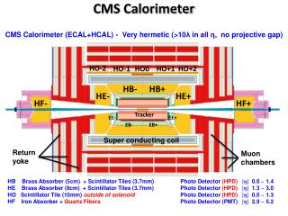
CMS Calorimeter Geometry EB, EE, HB, HE map to 18 RCT crates Provide e/g and jet, t, ET triggers
Calorimeter Trig. Algorithms • Electron (Hit Tower + Max) • 2-tower ET + Hit tower H/E • Hit tower 2x5-crystal strips >90% ET in 5x5 (Fine Grain) • Isolated Electron (3x3 Tower) • Quiet neighbors: all towerspass Fine Grain & H/E • One group of 5 EM ET < Thr. • Jet or t ET • 12x12 trig. tower ET sliding in 4x4 steps w/central 4x4 ET > others • t: isolated narrow energy deposits • Energy spread outside t veto pattern sets veto • Jet tif all 9 4x4 region t vetoes off
160 MHz point to point backplane 18* Clock&Control, 126* Electron ID, 18* Jet/Summary Cards all cards operate @ 160 MHz Use 5 Custom Gate-Array 160 MHz GaAs Vitesse Digital ASICs Phase, Adder, Boundary Scan, Electron Isolation, Sort (manufactured) *Spares not included Calorimeter Trigger Crate • Data from calorimeter Front End on Cu links@ 1.2 Gbaud • Into 126* rearReceiverCards
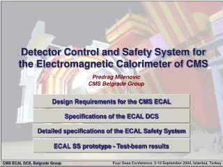
Crate & Backplane • 160 MHz differential ECL with 0.4 Tbit/sec dataflow • Tests indicate good signal quality • Designed to incorporate algorithms • Non-Isolated Electron, Tau & Jet Triggers VME 48V DC Power Std. VME Slots Custom Point-to-point Dataflow Rear Front Designed by J. Lackey
Clock & Control Card • Fans out 160 MHz clock & adjusts phase to all boards • ~90% of functionality tested successfully • Clock and Reset timing set with delay adjust Designed by J. Lackey Clock delay adjust DC-DC Converters
8 Compact MezzanineCards for each Receiver Card accept 4 x 20 m 1.2-Gbaudcopper pairs transmitting 2 cal. tower energies every 25 ns with low cost & power. Uses new Vitesse Link Chips (7216-01). Serial Link Test Card to check links Status: full production manufactured, currently in use for integration with ECAL New Cal. Trig. 4 Gbaud CopperLink Cards & Serial Test Card
4 x 1.2 Gbaud Copper Link Testing 20 m 22 AWG Copper Cable, VGA Connector Receiver mezzanine card Results:Bit Error rate < 10-15 Test Transmit mezzanine card Serial Link Test Cards
High Speed Custom ASICs • Custom ASICs • Vitesse FX™ and GLX™ gate arrays utilizing sub-micron high integration GaAs MESFET Technology • All I/O is 160 MHz ECL, except 120 MHz TTL input to Phase ASIC • All have JTAG on I/O, except Phase - only on output • All validated except EISO ASIC - requires a full crate of Receiver Cards • Phase ASIC • Receives four channels of 120 MHz TTL data via V7216-01 deserializer • Aligns & synchronizes the data, handles bit error detection • Can enable test vectors for checking data routes • Adder ASIC • Sums up the energy in the 4x4 regions • BSCAN ASIC • Drivers for data sharing, differential output • Sort ASIC • Receives differential input, sorts e/g and receives region sums (sort is optional) • EISO ASIC • Implements electron isolation algorithms
Calorimeter TriggerReceiver Card Calo In: 4 Chan. 24 bits: 2x9 data + 5 error • Full featured final prototype board is validated - production underway, boards manufactured for full crate test, 1422 mezzanine cards being manufactured. BSCAN & Self Test 9U x 400 mm mezz link cards VME Inter- Crate Sharing w/cables PHASE ASICs (validated) Adder ASICs (validated) BSCAN ASICs (Validated) AMP Stripline HD Conn. Designed by J. Lackey MLUs DC-DC Converters Top side with 1 of 8 mezzanine cards & 2 of 3 Adder ASICs Bottom side with all Phase& Boundary Scan ASICs • 32 Channels = 4 Ch. x 8 mezzanine cards with Vitesse 7216-1 1.2 GBaud copper receivers • V7216-1 deserializes data and sends • 120 MHz TTL to front Phase ASIC • Phase ASIC: Deskew,Mux @ 160MHz • Error bit for each 4x4, Test Vectors • Memory LUT @ 160 MHz • Adder ASIC: 8 inputs @ 160 MHz in 25 ns. • BSCAN ASIC: Provides Board BSCAN & Diff. Output@160 MHz to backplane
EISO SORT ASICs EISO Electron Isolation Card • Full featured final prototype board is validated and in production. • Processes 4x8 region @ 160 MHz • Uses Sort and EISO ASICs • Both tested by Vitesse before delivery • Sort ASIC used for Backplane Receive • Validated • Electron Isolation ASIC • Mostly validated • neighbor data for e/g isolation algorithm needs add’l RCs • Lookup tables for ranking • Highest energy isolated and non-isolated e/g per 4x4 region sent to Jet/Summary card for sorting, forwarding to Global Cal. Trig. Designed by J. Lackey
Jet/Summary Card • Summarizes full crate: • Electron/photon/muon • SORT ASICs receive data on backplane and find top four e/g (of 14 each isolated and non-isolated) • Threshold for muon Minimum Ionizing and Quiet bits (one per 4x4 region) • Data to Clustering/GCT • Forward Calorimeter (HF) functionality • Reuses Mezzanine Card to read in data directly for inclusion in output • LUTs for HF regions • Region energies • HF and 4x4 tower sums (regions) to cluster crate for central, t, and forward jet; calculation of global quantities total and missing ET • Under Test • HF path checked, • Data seen over backplane at Sort ASICs • 4x4 tower sum path checked to output Receiver Mezz. Card for HF Designed by J. Lackey DC-DC Conv. Region 4x4 and HF sums , e/g to GCT BSCAN ASICS Sort ASICS DC-DC Conv.
Pre-production Prototype Testing • Hand probing of boards • Timing of signals/clocks/resets checked • Data paths checked • Inject known data • Serial Test Card memories loaded and data sent on prototype cable • Receiver Card memories loaded & known data sent through Receiver Card and over backplane to Electron Isolation and Jet/Summary cards in "test" mode • Detailed use of JTAG to check data paths on board • Fully implemented on all boards and ASICs • Access JTAG through VME interface • Use to check ASIC to ASIC data paths in detail • Faster location of loose connections, bad solder joints • Can check backplane paths as well • Building JTAG fault library for Receiver, Electron Isolation, and Jet/Summary Cards for production testing • Producing code for uniform testing of cards • Easily handle multiple cards in a crate
Testing Receiver, Clock, EISO, & Jet/Summary Cards, Crate, & Backplane Front:Clock, EISO, and Jet/Sum Cards with original STC and cable to test HF data transfer to Jet/Summary card at full speed • 160 MHz TTL clockwith datainto 200 MHz Memories (2 ns scale) Crate Rear: Loopback Cables to test inter- crate data sharing
Conclusions • Final CMS Regional Calorimeter Trigger in production • Receiver Mezzanine Card • Full quantity including spares manufactured • Receiver Card and ASICs • Phase, Adder, BSCAN ASICs validated and full quantity procured • Electron Isolation Card and ASICs • Sort ASIC validated and full quantity procured, EISO ASIC needs a full crate test to test handling of neighbor data • Completing prototype tests • Crate, Backplane, CCC under test • Clock and Control Card nearly validated, Backplane & Crate need full complement of cards • Serial Link Test Card & Transmitter MC tested, produced • In use with ECAL serial link electronics • Jet/Summary Card under test • Goals for 2003/2004 • Complete prototype tests, validate last EISO ASIC, Jet/Summary Card • Full crate test in near future • Test interface with with Global Calorimeter Trigger • Continue production and integration tests