Download
1 / 24
240 likes | 266 Views
Explore the performance of the CMS Regional Calorimeter Trigger at TWEPP 2009, focusing on systems like Level-1 Trigger, detector front-ends, and event controls. Discover the operational details, latency, and algorithms contributing to the high-speed, dead-time free operation at CMS. Learn about the Regional Calorimeter Trigger's role in identifying trigger primitives and forwarding data for further analysis, ensuring efficient data processing and quality monitoring. Gain insights into the intricate architecture, mapping, algorithms, and clock systems employed to maintain the trigger's accuracy and reliability.

E N D
Performance of the CMS Regional Calorimeter Trigger • P. Klabbers, M. Bachtis, S. Dasu, J. Efron, R. Fobes • T. Gorski, K. Grogg, M. Grothe, C. Lazaridis, • J. Leonard, A. Savin, W.H. Smith, M. WeinbergPhysics Department, University of Wisconsin,Madison, WI, USA • TWEPP 2009 • September 23, 2009 • The pdf file of this talk is available at: • http://indico.cern.ch/contributionDisplay.py?contribId=100&sessionId=16&confId=49682 • See also the CMS Level 1 Trigger Home page at • http://cmsdoc.cern.ch/ftp/afscms/TRIDAS/html/level1.html
CMS Trigger & DAQ Systems • Level-1 Trigger • LHC beam crossing rate is 40 MHz & at full Luminosity of 1034 cm-2s-1109 collisions/s • Reduce to 100 kHz output to High Level Trigger and keep high-PT physics • Pipelined at 40 MHz for dead time free operation • Latency of only 3.2 msec for collection, decision, propagation Level-1 Detector Front-ends Trigger Readout Event Controls Switch Fabric Manager Farms Computing Services
The CMS Level-1 Trigger &Regional Calorimeter Trigger • Only calorimeter and muon systems participate in CMS L1 3<||<5 ||<3 ||<3 ||<2.1 0.9<||<2.4 ||<1.2 4K 1.2 Gbaud serial links Cu cables e/, jets, ET, HT, jet counts muons • Regional Calorimeter Trigger • Receives Trigger Primitives (TPs) from 8000 ECAL/HCAL/HF towers • Finds 28 e/g candidates, creates 14 central tower sums, 28 quality bits, and forwards 8 HF towers and 8 HF quality bits • All sent to Global Calorimeter Trigger (GCT) at 80 MHz on SCSI cables
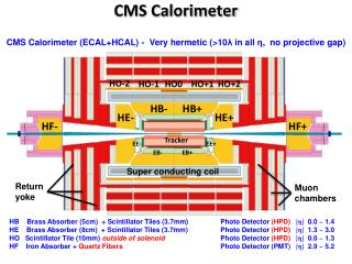
CMS Calorimeter Geometry EB, EE, HB, HE map to 18 RCT crates Provide e/g and jet, t, ET triggers
Calorimeter-RCT Mapping • 18 crates handle the entire CMS calorimeter seamlessly • Each crate covers a 0.7 f by 5 h region • Each Receiver - Electron ID Card pair covers a 0.35 f by 0.7 h region (ex. one 0.7 f by 0.5 h) • Single Jet/Summary card receives HF, finds 8 e/g, sets Quiet bits and forwards Sums, e/g, and all bits to GCT
Calorimeter Trig. Algorithms • e/g Rank = Hit+Max Adjacent Tower • Hit: H/E < Small Fraction • Hit: 2 of 5-crystal strips >90% ET in 5x5 Tower (Fine Grain) • Isolated e/g (3x3 Tower) • Quiet neighbors: all 8 towerspass Fine Grain & H/E • One of 4 corners 5 EM ET < Thr. • Jet or t ET • 12x12 trig. tower ET sliding in 4x4 steps w/central 4x4 ET > others • t: isolated narrow energy deposits • Energy spread outside t veto pattern sets veto • t Jetif all 9 4x4 region t vetoes off
RCT Crates Master Clock Crate (MCC) Main RCT Crate • One crate with 3 custom cards to create and fan-out 160 & 120 MHz clocks, ReSync, and Bunch Crossing Zero to 18 RCT Crates’ Clock & Control Cards • Clock Input Card (CIC) - 1/5* • Source: LHC clock or on-board Oscillator • Fine and course delay up to 25 ns • Clock Fanout Card to Crates (CFCc) & Clock Fanout Card Midlevel (CFCm) – 2/7* & 7/13* resp. • Fine delay adjust to all crates • Signals distributed on 36 4-pair low-skew cables of the same length. VME 48V DC Power 160 MHz Diff. ECL 0.4 Tbit Point-to-point Dataflow Designed by J. Lackey 18/26* crates with custom backplane incorporate algos: e/g, t & Jet Triggers *used/total produced
RCT Cards Clock & Control 18/25* - 1 per crate Receiver 126/158* - 7 per crate • Provides 160 MHz & 120 MHz clocks, reset, BC0 to one RCT crate, phase and delay adjustable. • Clock from Master Clock Crate fed by CMS Trigger Timing and Control (TTC) System Receives 128 E & HCAL towers on 1.2 GB Cu Links (Vitesse 7216-1) on RMC’s Phase, Adder, and Boundary Scan ASICs to realign/deskew data in, regional sums, sync 50 towers for e/g algo Memory LUT at 160 MHz Electron ID 126/157* - 7 per crate Jet Summary 18/25* - 1 per crate • e - g - m • Sort ASICs receive data on BP & find top iso. & non-iso.) • 14 Quiet Bits by threshold on JS • 14 MinIon bits from RC • Forward Calorimeter (HF) RMC & LUTs for HF ET’s • Regional (4x4 tower) sums to GCT • Sort (disabled) ASIC for BP receive and EISO ASIC fully implements e/g algorithm • Sends highest ET iso and non-iso e/g for 2 4x4 regions sent to JSC • 28 e/g candidates per crate via BP to JSC • 7x2 Iso & 7x2 Non-Iso *used/total produced
RCT Input and Output • HCAL HTR (HCAL Trigger and Readout) and ECAL TCC (Trigger Concentrator Card) use a Serial Link Board (SLB) with the Vitesse V2716-1 link chip • Configurable mezzanine card with 2 FPGAs synchronize data for V2716 • Separate SLB-RCT clock to ensures data in time between subsystems • HTR: max 6 SLBs send Trigger Primitives (TPs) • TCC: max 9 SLBs send TPs • TCC & HTR Receive front-end data on fibers ECAL TCCs HCAL HTRs RCT Rear SLBs RCT Front • Each RCT Crate to to 3.5 GCT Source Cards (SCs) • RCT sends diff. ECL - 6 SCSI cables/crate to SCs • SC sends data on fibers to main GCT crate • GCT turns regional sums to jet candidates, sorts jet and e/ candidates, computes missing ET, HT, jet counts and sends to Global Trigger (GT) SC Crate
RCT Trigger Supervisor Overview • CMS Trigger Supervisor (TS) • An online software framework to configure, test, operate, and monitor the trigger components and manage communications between (sub)systems • Set up as individual subsystem cells and a central cell directing multiple systems at once with SOAP commands • RCT Trigger Supervisor handles • System configuration via a pre-defined key for data taking, internal tests, and multi-system interconnection tests • Central configuration of trigger systems by CMS Run Control for data taking and interconnection tests or user configuration • Accesses DBs for configuration including channel masking • Interface for creating new keys • Provides feedback after transition RCT Configuration RCT Masking Tool
RCT Trigger Supervisor Monitoring • RCT Trigger Supervisor does crate monitoring • RCT hardware registers and errors in simple overview • Link errors, etc. in red • Can mask channels not in use in monitoring panel • Using a file or DB • Time-stamped values in DB • Alert and alarm functionality • Logs all runs with RCT • Provides list with key and run settings • Basic functionality • Individual crate operations • Single commands • Will include pattern test management • Controlled by Central TS • Multiple sub-system ops RCT Monitoring Panel RCT Run History
RCT Intercrate Testing • Uses the ability of the RCT to cycle the addresses of its input LUTs on the Receiver cards (emulates 64 crossings) • All 18 RCT crates used and GCT Source Cards capture output • Pattern into emulator to predict output and compare with capture • GCT Source Cards are very flexible - multiple capture options including BC0, output patterns, and ReSync • First tests were internal, testing timing between RCT crates • Check sharing on every edge, for every tower, timing tolerances • Walking zeros & ones, random, ttbar simulated data like • ttbar: Partial output at right • Problems found and fixed • Checked RCT-GCT connections • Will be integrated into TS • Developing tests using patterns injected at TPG level • Tests SLB-RCT link, algos.
RCT Trigger Emulator • Software with the goal of exactly reproducing the L1 Trigger hardware response, including: • Use and generate Look-Up Tables (LUTs) using decompression tables provided by HCAL and ECAL • Include Hardware and Firmware registers and any other configuration options • Access same database as TS to get configuration information • Used for hardware validation and monitoring • In use by the RCT to predict the response of the full system to trigger primitive data and pattern tests • Online and offline Data Quality • 18-Crate test (patterns injected at RCT LUTs) • Link tests (patterns injected at TP level) • In this way the hardware and the emulator are fully vetted • Bugs are tracked down and fixed in firmware, hardware and software • In reverse: simulation can be used to inject physics patterns into the hardware • Validation of algorithms
CMS Global Runs and Data Taking • In order to integrate detectors, fix problems, and be ready for data taking when the beam restarts • Use cosmic-ray muons, study noise rates, run high-rate random triggers to test DAQ capabilities, etc. • 2 days to several weeks at a time • Designated periods since Fall 2007 • Most recently ~1 month run at 4T – CRAFT 09 • All subsystems participate • RCT took part with HCAL and ECAL providing TPGs • ECAL ET with H/E-Fine Grain OR to e/g path • HCAL+ECAL ET to Sums path with activity bit for Tau Veto • Configurable LUTs allow entire detector or portions to be masked • e.g. hot trigger towers, HF out, etc. • RCT studies the data to validate algorithms and detect problems • Use Data Quality Monitoring – Online and Offline
Global Runs and Data Taking • CRAFT09 (Cosmic Run At Four Tesla) in August • Goal of 300M muons with full detector reached • Including calo trigger with physics LUTs – lots of valuable data Muon with calo hits Hz Run Number
RCT Data Quality Monitoring • Online: real-time histograms created and filled • Older runs available (all cosmic data) • Data delivered at a rate of ~1-10 Hz • L1 Trigger Summary Page has selected histos for trigger shifter to check Run Selection
RCT Data Quality Monitoring • Online - RCT selected histograms help monitor: • Problems like a ‘Hot’ or dead channel • Occupancy plots (right) of number of eventsper region • RCT regions distributed over h & f • h=0 between GCT eta 10 & 11 • Check rank of L1 candidates, etc. • Can be compared to a ‘reference histogram” – highlighted if in error • In addition, real time data validity checks with emulator – L1TEMU • Updated functionality • Histograms also highlighted • Level of errors reported per trigger subsystem on front page of DQM • Detailed histograms for each trigger subsystem’s experts • Accessed from L1T or L1TEMU summary page
RCT Data Quality Monitoring • Offline – prompt and more detailed analysis possible • Access to a greater number of events than online • Book more histos (e.g. indiv. channels) • Emulator uses HCAL and ECAL TPGs to predict results • Compared to RCT/GCT data to get eff. • Valuable debugging tool • Efficiencies reveal intermittent problems – Dark green is 100% efficient fbin hbin e/g Eff, rank (ET) matching by RCT region Region Eff, rank matching fbin fbin hbin h = 0 hbin
RCT Performance • During CRAFT09 – 24/7 running • Repeated configuration of the RCT at run start • No configuration errors due to hardware problems • 18 crates with >20x217 locations in LUTs • Rare computer crashes/hardware driver problems excluded • Rare software-related configuration errors • New versions of software packages address this • Monitoring of RCT performance • DQM online and offline evaluated daily • Caught problems early • Efficiencies show near-perfect hardware performance • Minor hardware issues repaired in time for restart of running and beam • Very few fixes during CRAFT running possible • Overall very stable operation ensured by diligence of RCT crew
Finally • CMS RCT operating throughout 2009 • Tools necessary for operation in place • RCT Trigger Supervisor to configure, monitor, and test the RCT • Integrated with Central Trigger Supervisor, controlled by CMS Run Control during daily data taking • DQM running stably • Plenty of data taking in 2009 • Usefulness of RCT DQM and emulator proven • Online and offline analysis to study RCT • Found problems early • RCT flexible • Not dependent on including complete calorimeter in run • RCT could mask sections or entire sub-detectors • Trigger Supervisor configuration keys set up for a variety of scenarios • Ensured RCT had copious data to analyze! • RCT performance solid • RCT is ready for colliding beams!
RCT Hardware Installation and Commissioning at CMS • One RCT Master Clock and 18 RCT crates tested and cards installed • All cabling installed: input HCAL, HF, ECAL, RCT internal data sharing, and output to GCT • Input cabling complete • Total: 1026 SLB-RCT Crate Rear Front of Racks Rear of Racks 56 ECAL/HCAL input cables per crate (Beige) 11 Data sharing connections per crate (Black) Full system = 19 Crates 18 HF input 108 Cables to GCT
Operations: Detector Slow Control and Rack Monitoring System Rack 1 Control Panel • One Custom-built Rack Monitor Card installed in July 2006 per rack: • Monitors power supplies, temperatures, fans • Configurable - alarm set points, number of fans, power supplies connected… • Ability to turn on and off system, check for and acknowledge alarms, send notification of… • Connects to network via a COMTROL serial-to-ethernet port • Slow Control software was developed using PVSS (Prozessvisualisierungs und Steuerungs-System) • Fully Implemented in USC55 • Exploits all above functionality • Keeps values in database • Histograms available • Fully integrated into CMS DCS Rack 1 Crate A Temperatures Rack Monitor Card and power chassis Power & Temp. Fans & Monitoring