CMS Calorimeter Trigger
CMS Calorimeter Trigger. GCT Muon Auxilliary Card Update Tom Gorski, Amin Farmahini-Farahani University of Wisconsin October 28, 2009. GCT Muon Aux Card Update. RS-232. AMC Edge Connector ( µTCA). TTS. Pushbutton Reset (for Microblaze). S-Link Connectors. TTCrx.


CMS Calorimeter Trigger
E N D
Presentation Transcript
CMS Calorimeter Trigger • GCT Muon Auxilliary Card Update • Tom Gorski, • Amin Farmahini-Farahani • University of Wisconsin • October 28, 2009
GCT Muon Aux Card Update RS-232 AMC Edge Connector (µTCA) TTS Pushbutton Reset (for Microblaze) S-Link Connectors TTCrx
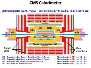
GCT Muon Aux Card • Provides SLINK-64, TTC and TTS Connectivity in a Single-Width, Full-height μTCA form factor • Xilinx Virtex-5 FPGA (XC5VLX110T) • 16 Rocket I/O GPT Links to edge connector • 1136-pin BGA Package • For connecting a μTCA crate to the TTC and DAQ subsystems
GCT Muon Aux Card Update • Testing Status: Design verification completed on TTS, S-Link, and Rocket I/O Interfaces. TTC checkout is in process • Testing performed on original 2 boards. More boards to be built after design verification completed • Boards will be shipped with a test program burned into Flash—connect via RS232 port/terminal • Test software/firmware should be completed by end of 2009 • Firmware is a HDL/Microblaze hybrid
GCT Muon Aux Card Update Two Aux Cards in Test Fixture Running a GTP Link Test (6 connections—4 passive, 2 through switches)
Aux Card Rocket I/O Testing • Link rate of 3.125 Gbps from 125.0 MHz oscillator • 8b/10b encoding, 16-bit parallel interface (156.25 MHz parallel clock) between GTP tile and FPGA fabric • Simplex connection between Transmitter and Receiver • Uses comma (K28.5) char for sync/byte alignment • Test Protocol: 32-byte header contains ID of Xmtting board/channel, test pattern descriptor • Rcvr compares incoming data stream to that specified by header, capturing/counting errors • X/R test blocks in HDL, run independently of processor • Some results using 64-bit LFSR pseudo-random pattern: • Single board loopbacks to different GTP Tile: continuous run of 5×1015 bytes with zero errors (~280 hrs on 16 simultaneous ch.) • Board-to-Board on Slots 0 & 3 of Test Fixture: over 2×1014 bytes with zero errors (~24 hrs on 6 channels)
Rocket I/O Test Program Output (Xmt Ch 4 to Rcv Ch 3) Rx Port Snapshot LFSR Pattern Bd/Ch ID (E4) Infinite Length Starting Seed Register Dump for Block 4 (uTCA port 11) Transmit Block Register Dump: Config: 0x00000013 ParamA: 0x45ECBB34 ParamB: 0x00000000 Length: 0x01000000 Status: 0x00000002 XCntH: 0x00004852 XCntL: 0x0CC2A276 Register Dump for Block 3 (uTCA port 4) Receive Block Register Dump: RCfg: 0x69780000 Config: 0x0000E413 ParamA: 0x45ECBB34 ParamB: 0x00000000 Length: 0x01000000 Status: 0x00000402 RCntH: 0x00004852 RCntL: 0x0998CF36 ErrCtr: 0x00000000 CapExData: 0x00000000 CapAcData: 0x00000000 CapRCtrH: 0x00000000 CapRCtrL: 0x00000000 CapErrCtr: 0x00000000 4-byte words Xmitted 4-byte words Rcvd/Verified Zero Errors