TCS Overview
TCS Overview. Welcome!. Texas City Site. BP Operations In Texas. BP ’ s regional headquarters are in Houston. It encompasses 24 business units with assets spanning 13 states.

TCS Overview
E N D
Presentation Transcript
Welcome! Texas City Site
BP Operations In Texas • BP’s regional headquarters are in Houston. It encompasses 24 business units with assets spanning 13 states. • Oil and gas exploration and production assets onshore and in the GoM, producing ~591,000 barrels of oil equivalent daily. • A Refinery that is the largest in BP’s system. • One chemical plant. • A share in 4,000 miles of pipelines that carry crude oil, refined products and petrochemicals. • ~10,000 BP and contract employees, including the drilling rigs and platforms in the GoM.
Texas City Refinery • ~24 Units With a Crude Oil Capacity of ~470,000 Barrels a Day • 1200 Acre Site (Approx. 2 square miles) • ~2002 Employees
What is Crude Oil? Crude oil is petroleum that occurs naturally in sedimentary rocks and consists mainly of hydrocarbons. Unrefined crude is a mixture of many hydrocarbons, varying in type, molecular weight, and boiling point. In its raw form, however, crude oil is of very little value. To make useful products, the oil must be separated into “cuts,” or fractions that contain similar types of hydrocarbons. This is accomplished by a process called distillation or fractionation. Distillation uses heat to separate this mixture of hydrocarbons according to their respective boiling point ranges. It is not practical to separate the crude oil into pure hydrocarbons. The consumer does not often need petroleum products that are essentially pure chemical components, but instead, fractions of the oil that have a wide boiling range. For the most part, crude is initially refined in a Pipe Still (crude distillation unit or CDU) to make the following products: gas (for fuel purposes or for outside sale), gasoline, naphtha, kerosene, furnace oils, gas oils for catalytic cracking unit feed, lubrication stocks, fuel oil, and coke.
How Does the Crude Get Here? Crude is delivered to the Texas City Refinery by pipelines and….
How Else Does the Crude Get Here? …marine shipments by crude carriers Very Large Crude Carriers bring oil from distant ports. Some are too large to come into the BP’s Marine Docks. Their cargo is offloaded to smaller ships in the Gulf of Mexico (GoM).
How Else Does the Crude Get Here? …by barges. Barges may also be used to offload VLCCs in the GoM. These operations require that shipments be planned and scheduled weeks in advance. Crudes are primarily described as high sulfur (sour)or low sulfur (sweet), heavy (low API gravity) or light (high API gravity) domestic or foreign crudes. In general, light crudes contain more naphthas and distillates, while heavy crudes contain more gas oils and resid.
The Crude Is Stored in Tanks The crude is segregated into several different tanks. API gravity and sulfur content are two common ways to segregate crude. Oil Movements provides a blend of these major categories and pumps it to the CDUs.
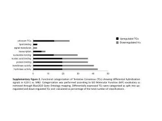
What’s in a ‘Barrel of Crude Oil’ and How We Change It. REFINED & PROCESSED PRODUCTS CRUDE OIL MAY CONTAIN 5% Light Ends 10% Light Ends & Chemical Feed Stocks 20% Gasoline 10% Kerosene/ Jet Fuel 60% Gasoline 15% Diesel / Furnace Oil 35% Gas Oil 25% Jet Fuel Diesel Furnace Oil 15% Resid 5% Resid / Asphalt / Coke
TCRs Major Product Flow Paths and Processing Units Benzene To Chemical Ultracrackate Toluene AU2 Aromatics Sales Recovery Ultraformate Unit Xylene Ultraformer Units 3&4 Ultraformate Ultraformate Ultraformate Hydrogen Units 1&2 AMOCO Naphtha ULTIMATE Crude Distillation Units (CDU) 3A & 3B Heavy Naphtha Blending Isomerate OEU Light Naphtha AMOCO Alkylate (Also called Pipe Stills) Hydrogen UNLEADED Alky 2&3 Light Ends REGULAR Distillate Naphtha Fluid Catalytic Cracking Units 1, 2 & 3 Cat Feed Unit (CFHU) Naphtha Desulfurizer GasOil H and Vapor Recovery 2 HRU Ultracrackate Ultracracker LCCO to Ultraformers 3&4 H 2 Distillate JET FUELS Gas Oil Distillate H Gas Oil 2 Desulfurizer Units Resid RHU DIESELS Blending Delayed Cokers Distillate 100, 200 & 300 Resid Distillate HEATINGOILS A/B/C Resid Asphalt RDU H 2 Coke Sulfur DA Oil Sulfur Recovery Unit FCU DCO Resid
Texas City’s products are moved by pipeline, marine vessels or are sold in Pasadena. Products are also sent to BP Texas City Chemicals for further processing. New Construction Pipeline Routes: Seaway Orion Colonial Phillips Explorer Kaneb & Chase TEPPCO Williams Marine Routes: Longhorn Aspen Gulf Coast Santa Fe Pacific
Texas City Refinery’sManufacturing Area Teams (MAT) • Crude and Cracking • Hydroprocessing • Systems
Texas City Refinery’sManufacturing Area Teams (MAT) • Crude/Cracking • Pipestill 3A & 3B • Coker A, B, & C • Residual Deasphalting (RDU) • Fluid Catalytic Cracking (FCCU 1, 2, & 3) • Alkylation (Alky 2 & 3)
Crude and Cracking MAT Crude Distillation Units – PS3A & 3B It doesn’t matter whether a refinery is simple or complex, the first process unit that the crude enters in a refinery is the crude distillation unit or pipe still. CDUs separate different fractions of hydrocarbons in crude by using temperature and pressure. Pipe Still 3, was originally placed on-stream in l96l and had a crude running capacity of l50,000 B/SD. Pipe Still 3B was built in 1967 to supply an increased product demand. Design rate was 70,000 BPD of 38º API crude and 30,000 BPD of 51º API condensate. PS3 then became PS3A.
Crude and Cracking MAT Crude Distillation Units – PS3A & 3B As the result of modernization expansions, de-bottlenecking, efficiency improvements, and advances in technology, the two units have a capacity of ~470,000 B/SD. • PS3 can be roughly divided into five sections according to the purpose they serve: • Atmospheric Crude Distillation Section • Gas Oil Fractionator Section (PS3A only) • Vacuum Distillation Section • Vapor Recovery Section • Treating Section (PS3A only) The atmospheric crude distillation section is the primary process on PS3A&3B. It is here that crude first enters the unit where it is heated, desalted, flashed and the initial separation of the crude oil takes place producing these products.
Crude and Cracking MAT Crude Distillation Units – PS3A & 3B Light and heavy gas oils are separated from resid in the Vacuum Distillation Section LVGO and HVGO flows hot CFHU (or to FCCU-1 or 3), or it is cooled and sent to tankage. “Wash oil" is used to prevent heavy coke and metals buildup in HVGO by washing the tray above its draw-off tray to prevent contamination of the HVGO product. These contaminants in gas oil severely effect catalyst efficiency at the cat crackers. Excess wash oil returns to the GOF tower (or crude tower). Resid is sent "hot" to the Cokers, RHU or FCCUs.
Crude and Cracking MAT Fluid Catalytic Cracking Units The Texas City Refinery has three Fluid Catalytic Cracking Units.
Crude and Cracking MAT Fluid Cat Crackers FCCU-1 was first placed in operation early in 1944. With upgrades and modifications, the unit can now feed ~60,000 B/D. FCCU-2 was brought on stream in early 1954 and has the capability to run straight crude with a capacity is ~40,000 B/D. It is presently idled. FCCU-3 began operation in 1962. Since that time, the unit has undergone many changes. The present feed capacity is ~123,000 B/D - making it one of the largest fluid catalytic cracking units in the world.
Crude and Cracking MAT Fluid Cat Crackers
Crude and Cracking MAT Alkylation Units & Sulfuric Acid Plant The Alkylation process is the reaction of isobutane with an olefin such as propylene, butylene, or amylene in the presence of an “acid” catalyst to produce a high octane gasoline blending component called “alkylate”. The Texas City Refinery has two Alkylation Units
Crude and Cracking MAT Alkylation Unit No. 3 Alky 3 is equipped with a remotely controlled “Mitigation System” to protect TC Site personnel from an HF release within the Alky 3 battery limits. Mitigate means to cause to become less harsh or hostile. It consists of a water storage tank, six very large water supply pumps, supply piping, fixed spray headers and water cannons to create a water curtain to absorb the HF. (Photo shows system being tested.) It is also equipped with a 30 point, leak detection system that automatically activates and alarms. The HF Mitigation System is an effective way to neutralize and control an accidental HF acid release.
Crude and Cracking MAT Coker Complex Cokers A, B, & C process resid that has an API gravity of 3.1-9.4 (heavy oil) into coke, gas oil, naphtha, gasoline & other products.
Crude and Cracking MAT Coker Complex – Coke Drums The feed to the three coking units consists of resid from the Pipe Stills and the RHU, and asphaltenes from the RDU. The feed is heated and charged to one of two coke drums, where through time, temperature, and pressure, the resid is cracked into coke and hydrocarbon vapors. The coke from the cracking process remains in the coke drum. One coke drum is in service always receiving hot hydrocarbons from the furnace. The other drum is being “decoked,” meaning its coke is being removed with high-pressure water. The lighter hydrocarbons flow out the top of the drum to the Combination Tower.
Crude and Cracking MAT Coker Complex – Combination Tower Vapors flow from the in-service coke drum to the bottom section of the Combination Tower – a distillation column. The hydrocarbons condense and fractionate as the heat is removed in the tower. Heavy-Heavy Gas Oil (HHGO) is feed to the CFHU / FCCUs. The Heavy Gas Oil (HGO) is feed for the CFHU or FCCUs or it is cooled and sent to storage. The Light Gas Oil (LGO) is routed to the DDU or to storage. The naphtha flows to the Coker’s Vapor Recovery Unit (VRU) for processing. The Wet Gas flows to the Wet Gas Compressor at the VRU.
Crude and Cracking MAT Coker Complex - Resid Deasphalting Unit The RDU was constructed during 1992. It increases the flexibility, efficiency, and profitability of processing heavy crude oils. The RDU removes solids (catalyst fines & asphalt) from the feed stream for the Resid Hydrotreater Unit (RHU). The RDU is also called the ROSE Unit for Residuum Oil Supercritical Extraction. This is a pentane solvent extraction process that recovers deasphalted oil (DAO) from the feed. After the solvent is mixed with the feed, it attracts the DAO and rejects the asphaltenes (ASP). The solvent is then separated / stripped from the DAO and ASP and reused. Clean DAO flows to the RHU or tankage. The asphalt is sent to the Cokers.
Texas City Refinery’sManufacturing Area Teams (MAT) • Hydroprocessing • Resid Hydrotreater (RHU) • Distallate Desulfurizer (DDU 100, 200, & 300) • Ultracracker (ULC) • Cat Feed Hydrotreater (CFHU) • Hydrogen Recovery (HRU) • Ultraformer (UU3 & UU4) • Aromatics Recovery (ARU & AU2) • Naphtha Desulfurizer (NDU) • Sulfur Recover Unit (SRU)
Hydroprocessing MAT Resid Hydrotreating Unit The RHU became operational in 1984. It processes resid to remove most sulfur, nitrogen and metals. The unit produces low sulfur resid, gas oil, distillates, gasoline and light ends.
Hydroprocessing MAT Resid Hydrotreating Unit The RHU consist of 3 parallel trains each equipped with 3 reactors that operate in series. The unit processes a mixture of: (1) high sulfur resid from PS3B, (2) DAO from the RDU, and (3) DCO from the FCCUs using special catalysts in circulating bed reactors in the presence of hydrogen. Demetalization catalyst is used in the 1st reactor to remove heavy metals and a desulfurization catalyst is used in the 2nd and 3rd reactors to remove sulfur. A relatively cold sponge oil and H2 gas are injected between reactors to quench the stream as the reaction is exothermic.
Hydroprocessing MAT Resid Hydrotreating Unit The Reactant liquid and vapors from the Reactor Section are fed to the Fractionation Section to be separated into various products. First is the Atmospheric Tower that produces several useful products. • Unstable Naphtha, which goes to the Vapor Recovery Section • Heavy Hydrotreated Naphtha (HHN) • Light Distillate • Middle Distillate • Light Gas Oil • The bottoms are sent to the Vacuum Tower to separate more products
Hydroprocessing MAT Resid Hydrotreating Unit The bottoms from the Atmospheric Tower flows to the RHU Vacuum Tower. The Vacuum Tower produces several useful products. • Overhead Vapors to the Vacuum Ejectors and Condensers • Vacuum Naphtha • Light Vacuum Gas Oil • Heavy Vacuum Gas Oil • Low Sulfur, Low Metals Resid
Hydroprocessing MAT Hydrogen Recovery Unit The HRU was started up in 1992. It separates hydrogen from off-gas streams that flow from the RHU. The HRU produces three products: (1) 96% H2 for the high purity H2 Header (2) low pressure fuel gas sent to the sweet fuel gas header (3) propane rich LPG that flows to the Debutanizer tower at the RHU The HRU cryogenically separates H2 from the feed gas in a series of phase separations. Cold box refrigeration is obtained by compression, cooling and expansion of the liquefied hydrocarbons, and of the hydrogen. External refrigeration is also used for initial cooling of the gases. Temperatures of -290°F are achieved, which can liquefy methane. The unit also removes most trace impurities such as H2O, NH3, H2S, CO2, NO2, and benzene from the H2.
Hydroprocessing MAT Cat Feed Hydrotreating Unit The CFHU processes heavy, high sulfur gas oils. It removes most sulfur, nitrogen and metals producing low sulfur gas oils for FCCU feeds.
Hydroprocessing MAT Cat Feed Hydrotreating Unit The CFHU consists of 2 parallel trains each equipped with 2 reactors that operate in series. It was started up in 1983. CFHU processes gas oil from: (1) PS3B HVGO (2) Heavy Coker Gas Oil (3) RHU Gas Oil (4) Utility Gas Oil The gas oil feed is mixed with hydrogen before entering a fired heater. The direction of the 2-phased flow is down through the reactor vessel. Each reactor has two beds of nickel-molybdenum catalyst using H2 quench for temperature control as the reaction is exothermic.
Hydroprocessing MAT West Plant
Hydroprocessing MAT Distillate Desulfurizer Units The DDU-100/200/300 uses reactors to remove sulfur & N2 from diesel & middle distillates. This is accomplished by combining it with hydrogen, then heating and passing the mixture through the two fixed bed reactors in series containing cobalt molybdenum catalyst. The reactor effluent is cooled, condensed and separated. The gas flows to DDUs Amine Contactor where the H2S/NH3 is removed. Liquid flows to a Stripper. Naphtha is sent to UU3 and low sulfur diesel flows to tankage.
Hydroprocessing MAT Ultraformer Unit No. 3 & 4 Both Ultraformers use a catalytic reforming process for producing a high octane gasoline blending product from low octane naphthas. The Ultraforming process uses a special platinum-on-alumina catalyst in fixed bed reactors. The main sections of the unit include the following: Feed Preparation & Desulfurization, Pre-fractionation, Ultraformer Furnaces & Reactors and Product Recovery. The Texas City Refinery Has Two Ultraformer UnitsAs Part of the West Plant
Hydroprocessing MAT Ultracracker Unit The ULC was placed in service in 1969 and is presently capable of processing 65,000 B/D of Mid-Virgin Distillate, Light Catalytic Cycle Oil, Desulfurized LCCO, Wild Kerosene, and Light Vacuum Gas Oil into light & heavy Ultracrackate, which is a feedstock for the Ultraformers and Aromatics Units. Other products manufactured are ethane, propane, butane, pentane and hexane and distillate.
The ARU-A side was started in 1968 at 50,000 B/D and the B side was added in 1975. It primarily feeds high octane ultraformate (naphtha) from the Ultraformers. Other feed streams include mixed xylenes from the Paraxylene units at the BP Texas City Chemical Site, pentane from Alky 2, and a crude benzene from other refinery units. Ultraformate and the other feed streams consist of aromatics and non-aromatic hydrocarbons. AU2 converts toluene, mostly from the ARU but may also be imported, into “paraxylene-rich” xylene & high purity benzene in a catalytic reactor in the presence of hydrogen. As a side reaction, some fuel gas is also produced. Hydroprocessing MAT Aromatics Recovery Units A&B Aromatics Unit No. 2
Hydroprocessing MAT Sulfur Recovery Unit Many different forms and amounts of sulfur are found in crude oils: elemental sulfur, hydrogen sulfide (H2S), mercaptans, and complex compounds. When burned, these sulfur compounds form sulfur dioxide (SO2) and sulfur trioxide (SO3) which are corrosive and air pollutants. At many of the refinery units, the liquid hydrocarbon stream is heated and changed to a gas. Then, in the presence of hydrogen (H2) and a catalyst, sulfur is converted into H2S. The H2S can then be removed from the gas. How is this done? Hydrocarbon gas streams containing H2S are treated by “scrubbing” with a solution of mono-ethanol-amine (MEA, or amine for short) that comes from the SRU. The amine absorbs the H2S and from the hydrocarbon stream. This is called “rich” amine, which returns to the SRU.
Hydroprocessing MAT Sulfur Recovery Unit – Sulfur Trains Acid gas that did not condense flows to a thermal reactor (furnace) and then through a series of catalytic reactors. This is called the “CLAUS” process. The H2S is partially burned (without excess air) to form sulfur dioxide (SO2) and water. The SO2 then reacts with part of the unburned H2S to form elemental sulfur. Hot combustion gases from the thermal reactor enter a condenser and are cooled (somewhat) by water that generates steam. The condensed sulfur flows to a pit. Hot gas then flows through a series of catalytic reactors where additional sulfur conversion takes place in the presence of a catalyst. Between each reactor is a condenser that cools the gas and generates steam. Condensed sulfur is drained to the sulfur pit. The tail gas then flows to the two SCOT units.
Hydroprocessing MAT Sulfur Recovery Unit – SCOT Units Tail gas from the sulfur trains flows to the SCOT Units where it is combusted with natural gas, air and H2. The hot gas flows into the SCOT reactor where the SO2 and other sulfur compounds are converted to H2S using a catalyst and the surplus H2. The hot gas is cooled by water that generates steam in a waste heat boiler (WHB) and then flows to a Quench Tower for final cooling.
Hydroprocessing MAT Sulfur Recovery Unit – SCOT Units In the Quench Tower, the gas is cooled by quench water. Most of the water vapor in the gas is condensed and additional heat is removed. The gas then flows to an Absorber Tower. The Absorber utilizes lean methyl-di-ethanol-amine (MDEA) to absorb the H2S from the gas. Gas from the Absorber Tower flows to the Incinerators for final oxidation of the remaining sulfur compounds. Rich MDEA is heat regenerated in the the Stripper Tower making lean MDEA for re-use. Stripper acid gas flows back to the sulfur trains for treatment.
Hydroprocessing MAT Sulfur Recovery Unit – Sour Water Strippers At the SRU, two Sour Water Strippers (SWS) remove ammonia (NH3) and H2S from the sour water produced at the RHU / CFHU / VRU. Heat drives off the absorbed NH3/H2S from the sour water. This acid gas flows to the sulfur trains for conversion. After stripping, “sweet water” is returned to the units for re-use. The SWS towers can be operated in parallel or series.
Texas City Refinery’sManufacturing Area Teams (MAT) • Systems • Oil Movements / Blending • Marine Docks • Environmental Facility (WWTP) • Utilities
Systems MAT Oil Movements Tank Farms & Shipping The first 69 tanks and the marine docks were constructed in 1933 when the Texas City Refinery first began operation and shipped the first product the following year. OM now operates over ~170 tanks with a total capacity of ~24,000 MMBBL with a working capacity of ~18,000 MMBBL, which includes three 750 MBBL storage tanks and more than 250 pumps. As the refinery expanded, new tanks were added and older riveted seam tanks were demolished. An automated OM Control Center became operational in 1967. OM manages crude oil receipts, crude tankage and operates the feed station for crude blends to the PS3A&B. They support all unit operations by maintaining unit to unit transfer lines, unit products to tankage, unit feeds from tankage, removal of water from tanks and controls inventories. They handle all refinery generated slop oils, which are dewatered and charged to the cokers or transferred to crude tankage.
Systems MAT Oil Movements Blenders & Docks OM operates the gasoline and distillate blenders to combine unit products (blending components) into finished products. OM ships finished products by pipelines and coordinates product shipments with the Marine Docks. The Marine Docks expanded operations in 1975 that increased the capacity of the Texas City Port by 50%. They can accommodate barges and up to 1,090-foot tankers, with a maximum unloading rate of 30,000 barrels an hour. The Docks handles shipping and receipts for the BP Refinery, BP Chemicals, Marathon Refinery, Valero Refinery and Dow Chemicals.
Systems MAT Utilities Potable water is supplied from the Texas City Municipal Water System, stored in tankage and pumped throughout the site for use in safety showers, eye washes, kitchens and toilets. Potable water that has been used in sinks and rest rooms flows to a sanitary sewer system for treatment. Utilities also monitors and controls Brazos river water (supplied from the Galveston County Water Authority) to the site, which is used to make service water, fire water and boiler feed water (BFW) for making steam. The river water is treated, filtered, stored in tankage and then pumped throughout the site for use as service water, which has many uses in the site with the primary use being cooling tower make-up. Fire water pumps take suction on the service water system and distribute the water through underground lines to fire water hydrants and deluge systems.