Feedback Principles and System Analysis in Electrical Engineering
This document provides an overview of key concepts in feedback systems, focusing on representation, analysis, and high-frequency dynamics. Key topics include open and closed-loop systems, damping factors, undamped natural frequency, and frequency response. The lecture explores significant parameters such as gain, stability measures, and response characteristics. Practical examples illustrate the effects of damping factors on system behavior, aiding in the understanding of phase margins and transfer functions essential for graduate-level electrical engineering students.

Feedback Principles and System Analysis in Electrical Engineering
E N D
Presentation Transcript
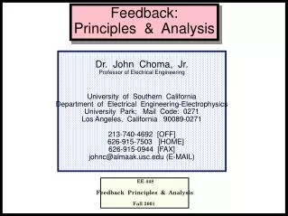
Feedback: Principles & Analysis Dr. John Choma, Jr. Professor of Electrical Engineering University of Southern California Department of Electrical Engineering-Electrophysics University Park; Mail Code: 0271 Los Angeles, California 90089-0271 213-740-4692 [OFF] 626-915-7503 [HOME] 626-915-0944 [FAX] johnc@almaak.usc.edu (E-MAIL) EE 448 Feedback Principles & Analysis Fall 2001
Overview Of Lecture • Feedback • System Representation • System Analysis • High Frequency Dynamics • Open And Closed Loop Damping Factor • Open And Closed Loop Undamped Natural Frequency • Frequency Response • Phase Margin • High Speed Transient Dynamics • Step Response • Rise Time • Settling Time • Overshoot 65
Open Loop Model • Gain: • Parameters • Zero Frequency Gain • Frequency Of Zero • Frequency Of Dominant Pole • Frequency Of Non–Dominant Pole • Frequency Of Zero Can Be Positive (RHP Zero) Or • Negative (LHP Zero) • Note That A Simple Dominant Pole Model Is Not Exploited • Input And Output Variables • Input Voltage Or Current Is X(s) • Output Voltage Or Current Is Y(s) 66 3
s s 1 – A (0) 1 – z z ol o o A (s) = A = ol ol s s 2 2 s 1 + 1 + ol p p 1 + s + 1 2 2 nol nol p p 1 2 1 = + ol 2 p p 1 2 = p p nol 1 2 ol ol ol Open Loop Transfer Function (0) • Damping Factor: • Measure Of Relative Stability • Measure Of Step Response Overshoot And Settling Time • Undamped Natural Frequency: • Measure Of Steady State Bandwidth • Measure Of "Ringing" Frequency And Settling Time • Poles • Dominant Pole Implies • Complex Poles Imply • Identical Poles Imply >> 1 < 1 = 1 67 4
s s f A (0) 1 – T (0) 1 – z z ol o o T (s) = f A (s) = = ol s s 2 2 s 1 + 1 + ol p p 1 + s + 1 2 2 nol nol s A (0) 1 – z cl o A (s) = cl 2 2 s cl 1 + s + 2 ncl ncl Closed Loop Transfer Function • Loop Gain (Return Ratio w/r To Feedback Factor, f ): • Closed Loop Gain: Obtained Through Substitution Of Open Loop Gain Relationship Into Closed Loop Gain Expression 68
s s 1 – A (0) 1 – z z ol o o A (s) = A = ol ol s s 2 2 s 1 + 1 + ol p p 1 + s + 1 2 2 nol nol s A (0) 1 – z cl o A (s) = cl 2 2 s cl 1 + s + 2 ncl ncl T (0) ol nol = – T f A cl ol 2 z 1 + T (0) 1 + T (0) o = 1 + T (0) ncl nol 1 A (0) cl f Closed Loop Parameters (0) • Closed Loop Damping Factor: • Closed Loop Undamped Frequency: • "DC" Closed Loop Gain: • T(0) Large For Intentional Feedback • T(0) Possibly Large For Parasitic Feedback (0) (0) 69
T (0) ol nol = – = 1 + T (0) cl ncl nol 2 z 1 + T (0) 1 + T (0) o Closed Loop General Comments • Damping Factor • Potential Instability Increases With Diminishing Damping Factor • Potential Instability Strongly Aggravated By Large Loop Gain • Note: Open Loop Damping Attenuation By Factor Of • Square Root Of One Plus "DC" Loop Gain • For Intentional Feedback Having Closed Loop Gain Of (1/f ), • Worst Case Is Unity Gain (f = 1), Corresponding To Maximal T(0) • Open Loop Zero • Closed Loop Damping Diminished, Thus Potential Instability • Aggravated, For Right Half Plane Open Loop Zero • Closed Loop Damping Increased, Thus Potential Instability • Diminished, For Left Half Plane Open Loop Zero • Undamped Frequency • Measure Of Closed Loop Bandwidth • Closed Loop Bandwidth Increases By Square Root Of One Plus • "DC" Loop Gain, In Contrast To Increase By One Plus "DC" Loop • Gain Predicted By Dominant Pole Analysis 70
n Step Response Example Of Damping Factor Effect Transmission Zero Assumed To Lie At Infinitely Large Frequency t 71
–1 –1 –1 ) = – tan – tan – tan z p p o 1 2 T(0) p u 1 u k k – 1 p o z = k p = k o o u 2 p u k + k p o 1 + k T(0) –1 –1 tan tan m T(0) – k k k o p Phase Margin ( v • Unity Loop Gain Frequency • Assumes Frequencies Of Zero And Second Pole Are Larger Than • Substitutions: • Phase Margin • Difference Between Actual Loop Gain Phase Angle And –180; • A Safety Margin For Closed Loop Stability • Approximate Phase Margin: • Since Can Be Negative, k Can Be A Negative Number • Result Is Meaningful Only For k (k) > 1 72
Phase Margin Characteristic Phase Margin (deg.) 120 100 T(0) = 1 80 T(0) =5 60 40 20 T(0) = 100 0 k -1 -0.8 -0.6 -0.4 -0.2 0 0.2 0.4 0.6 0.8 1 1.2 1.4 1.6 1.8 2 2.2 2.4 2.6 2.8 3 -20 -40 -60 73
s p = k A (0) 1 – T(0) p z = k 2 p u z cl u 1 o o u o A (s) = k k – 1 cl 2 p o 2 s cl 1 + s + k + k p o 2 ncl ncl p p 1 2 1 = + ol 2 p p 1 2 p p = 1 + T (0) nol 1 2 ncl nol k 1 1 1 p = k T(0) 1 – + 1 1 – cl p k 2 k 2 k T (0) 1 + T (0) o o p k 1 + T (0) p = k ncl u u p T(0) 1 + k T(0) –1 –1 tan tan m T(0) – k Circuit Response Parameters k = l Closed Loop Damping Factor: l Closed Loop Undamped Frequency: l Phase Margin: (k) 74
/ > 1 2 cl k 1 1 p 1 – k > 3.125 cl p 2 k 2 o k k – 1 p o k = k = 1.8 k + k p o 1 + k T(0) –1 f tan f 63.2 8 m m T(0) – k • Given: • Desire Maximally Flat Closed Loop Response, Which • Implies • Computations: • Requisite Phase Margin: • In Practical Electronics, Phase Margins In The 60s Of Degrees • Are Usually Mandated, Which Requires That The Non-Dominant • Pole Frequency Be 2.5 -To- 4 Times Larger Than The Unity • Gain Frequency Closed Loop Example Calculation 75
s A (0) 1 – z cl o A (s) = cl 2 2 s cl 1 + s + 2 ncl ncl 2 1 – dcl ncl cl z k o o M k ncl p x ncl y (t) y n A (0) cl y (t) 1 – A (0) cl s 1 – z Y (s) o Y = n A (0) 2 2 s cl cl s 1 + s + 2 ncl ncl Closed Loop Step Response: Problem Formulation • Problem Setup: • (Damped Frequency Of Oscillation) • Normalized Variables: • (Normalized Time Variable) • (Output Normalized To Steady–State Response) • (Error Between Steady State And Actual • Output Responses) t (t) (t) (s) 76
s 1 – z o Y (s) = n 2 2 s cl s 1 + s + 2 ncl ncl y (t) = 1 – n 1/2 2 1 + 2 M + M – x 2 cl e (x) = Sin x 1 – + cl cl 2 2 M 1 – cl x ncl z k o o M k ncl p 2 M 1 – –1 cl = tan 1 + M cl cl z + > 0 o cl ncl Closed Loop Step Response: Solution (t) • Solution: • Assumptions: • (Underdamped Closed Loop Response) • (Satisfied For Right Half Plane Zero) t < 1 77
Closed Loop Step Response Example #1 M = 1 78
Closed Loop Step Response Example #2 M = 5 79
1/2 2 1 + 2 M + M – x 2 cl e (x) = Sin x 1 – + cl cl 2 2 M 1 – cl y (x) = 1 – n x m m m m Closed Loop Settling Time (x) • Observations • Magnitude Of Error Term Decreases Monotonically With x • Maxima Of Error Determined By Setting Derivative Of Error • Term With Respect To x To Zero • Maxima Are Periodic With Period • First Maximum Of Error Establishes Undershoot Point • Determine Second Maximum And Constrain To Desired Minimal Error • Procedure • Let Be The Normalized Time Corresponding To Second • Error Maximum • Let Be The Magnitude Of Error Corresponding To • If Is The Desired Settling Error, Represents The Settling Time • Of the Circuit x 80
1/2 2 1 + 2 M + M – x 2 cl e (x) = Sin x 1 – + cl cl 2 2 M 1 – cl y (x) = 1 – n 2 1 – 1 –1 cl x = + tan m + M 2 1 – cl cl 2 1 + 2 M + M – x cl e = cl m m M 2 x m 4 – k 2 1 – p cl k p exp – m 4 – k p Closed Loop Settling Time Results (x) • Results: • For Large M (Far Right Half Plane Zero): 81
k p exp – k p m 4 – k p 2 x = t 2 m ncl m ncl 4 – k p k 2 ncl u p u –1 f tan ( k m p Closed Loop Settling Time Example • Requirements • Settling To Within One Percent In 1 nSEC • Assume Zero Is In Far Right Half Plane (Reasonable • Approximation For Common Gate And Compensated Source • Follower; First Order Approximation For Common Source) • Assume Very Large "DC" Loop Gain • Computations • Second Pole Must Be At Least 2.7 Times Larger Than • Unity Gain Frequency • Required Phase Margin: 0.01 > 2.73 ; = 5.575 (887.2 MHz) ; (537 MHz) ) = 69.9 82