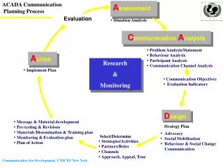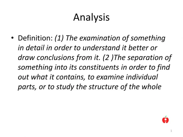
Analysis
Analysis. Principles Specification Unified modeling language Requirements analysis with use cases Domain modeling with class diagrams Dynamic modeling with sequence diagrams Visual Modeling.

Analysis
E N D
Presentation Transcript
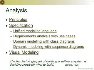
Analysis • Principles • Specification • Unified modeling language • Requirements analysis with use cases • Domain modeling with class diagrams • Dynamic modeling with sequence diagrams • Visual Modeling • The hardest single part of building a software system is deciding precisely what to build.- Brooks, 1975
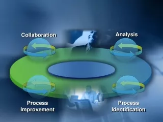
A Similar Story (in pictures) A Story
Reasons Cited for Project Failure Data from http://www.scs.carleton.ca/~beau/PM/Standish-Report.html
Principles • Analysis asks “what?” questions not “how?” questions. • It involves two UP disciplines: • Business modeling • Requirements • The requirements will change.
Types of Requirements • Functional requirements • Usability • Reliability • Performance • Supportability • Other: • Implementation • Interfaces • Operations • Packaging • Legal
Characteristics of Requirements • Stakeholder-centered • Precise • Consistent • Complete • Realistic
Stakeholders • Determine the stakeholders in the project. • Stakeholders on the customer side have trouble distinguishing: • what they want vs. what they need • what is vs. what could be
Precision • Distinguish between: • Desires • wishes of the customer/user • e.g., “it should be fast” • Requirements • detailed specs for the designer • e.g., “it should respond in less than 3 seconds in the typical user's environment.” • Requirements must be precise enough to be testable.
Prototypes can overly restrict design choice. • Use a consistent level of detail. Levels of Detail • Avoid using too much design detail in inception. images from J.C. Tarby
Consistency • Requirements are usually written in natural language, which can be ambiguous. • Get rid of ambiguity by: • using precise terms • having stakeholders review the text • stating things only once
Completeness • List all the requirements you can. • Prioritize them if necessary: • Normal requirements • Expected requirements • Exciting requirements
Elicitation Techniques • Holding interviews • Running workshops • Distributing questionnaires • Studying written documents • Writing task narratives • Performing ethnographic observations • Building mockups and prototypes
Specification • Requirements must be recorded. • We will produce artifacts that specify: • The functional requirements • The domain model
Specification Techniques • Informal approaches • Semiformal approaches • Formal approaches
The Unified Modeling Language • UML is a visual language for specifying, constructing and documenting the artifacts of systems. • Characteristics: • A collection of diagramming languages • Non-proprietary • Semi-formal • Object-oriented • Process-neutral
Outline • Modeling • History • Diagrams • Example • Using UML
image from http://ralfshome.virtualave.net/ Who cares about models? • A Model is a formal representation of certain aspects of the world. An architectural blueprint is a model
Modeling: Architecture • Models are representations of certain aspects of the world. Images from Calvin College, August, 2005
Modeling: Systems • Models are representations of certain aspects of the world. System database
Modeling and Reality • Blueprints aren’t buildings. • Models aren’t systems. Cecin’est pas un système. Image from www.wikipedia.org, August, 2005
The Three AmigosUnified Modeling Language • Each amigo (and dozens of others) had created their own modeling languages / processes in the 1980’s. • They joined forces at Rational in the mid-90’s to create a “Unified” Modeling Language. Grady Booch Ivar Jacobson James Rumbaugh Images from www.rational.com, January, 2003
OMG UML Standards • The OMG, a non-profit consortium of companies, produces and maintains standards. • UML Standards: • UML 2.0 Superstructure, 2004 • UML Profiles • Real-time profile, 2005 Images from www.omg.org, August, 2005
UML Tools There are many tools that support UML: • IBM Rational Rose • iLogix Rhapsody • Microsoft Visio • Sparx Enterprise Architect • …
Diagramming Languages • UML Diagramming languages provide various views on a single meta-model. • These views are loosely organized into the following types of diagrams: • Structural • Behavioral • UML 2.0 includes 13 languages.
Example: Use-Case Diagram Example from www.ilogix.com, August, 2005
Example: Class Diagram Example from www.ilogix.com, August, 2005
Example: State Diagram Example from www.ilogix.com, August, 2005
Example: Compilation Example from www.ilogix.com, August, 2005
Example: Execution Example from www.ilogix.com, August, 2005
Using UML Language = syntax + semantics + pragmatics • 20% of UML is used 80% of the time. • UML can model garbage or gold with equal ease.
Using UML: Why? • Conceptual modeling • Software modeling
Using UML: How? • Sketch • Blueprint • Programming language
Using UML: Directionality • Forward engineering • Reverse engineering • Round-trip
UML and Software Process • UML fits naturally into traditional software development processes. • UML is also compatible with agile development processes:
Criticisms of UML • UML is often seen as: • too informal • too big • not big enough • Bell, Alex E., “Death by UML Fever”, ACM Queue, 2(1), March, 2004.
Use Case Analysis • Use case analysis identifies the intended behavior of the system from the user’s perspective. • Use cases are written scenarios that describe a case of the use of the system. • Use case diagrams are visual representations of the actors, use cases, and their interrelationships.
Example: Scenario • The customer revisits the Think Geek website, searches for a geeky item they can’t live without, and orders that item. The system maintains a shopping cart with that item. The customer confirms the credit card and shipping information they entered before and then confirms the sale. The system then executes the sale. Example adapted from Fowler, 2003
Example: Use Case • Description • The customer buys a product from the on-line store. • Primary Actor • Registered Customer • Preconditions • The customer can access the website. • Postconditions • On-line sale is recorded and confirmed. • The customer's database history is updated.
Example: Use Case (cont.) • Main Scenario: • The customer browses through the products. • The customer adds a product to their shopping cart. • The system displays the shopping cart with the new product. • The customer logs in and proceeds to check out. • The customer confirms their credit card and shipping information. • The customer confirms the order. • The system validates the credit payment. • The system makes the sale. • The system confirms the sale immediately and via email.
Example: Use Case (cont.) • Extensions 2a. The database reports that the product is out of stock. 1. The system marks the shopping cart entry as back order. 4a. User is a new (unregistered) customer. The system displays the shopping cart with the new product. 1. The system displays a welcome message. 2. The customer enters their payment and shipping information.
Outline • Use Case Diagrams • Actors • Use cases • Relationships • Using Use Case Diagrams
Actors • Use case actors carry out use cases. • They represent roles played by: • Human users • Other systems or processes
Use Cases • A use case is a set of scenarios all achieving the same high-level goal. • They focus on functionality, not interfaces. • Fully dressed use cases can include fields for:
Use Case Relationships • Association • Include • Extend • Generalizes
Using Use Case Diagrams • Focus on the written use cases, not on the diagrams. • The written narratives are natural tools for creating understanding. • Use the description field of a use case to: • Prioritize the use case and the steps within it according to value and risk. • Add any non-functional requirements relevant to that use case.
Classes and Objects • Objects are entities that have attributes, behavior and state. • Classes are sets of objects with common properties and behavior. • Classes and their interrelationships implement the 3 key elements of object-oriented programming:
Class and Object Diagrams • Class diagrams: • are the most common UML diagram • model classes and the static relationships between them • Object diagrams: • are less common • model a snapshot of the system objects at some time
Example: Class Diagram Example adapted from Fowler, 2003