Exploring Atomic Force Microscope: Imaging Modes & Working Principle
Understand the principles of Atomic Force Microscope (AFM) and its imaging modes such as Contact, Tapping, and Non-contact, enabling high-resolution imaging and force measurement at the atomic scale. Learn the components, setup, and feedback control essential for AFM operation.

Exploring Atomic Force Microscope: Imaging Modes & Working Principle
E N D
Presentation Transcript
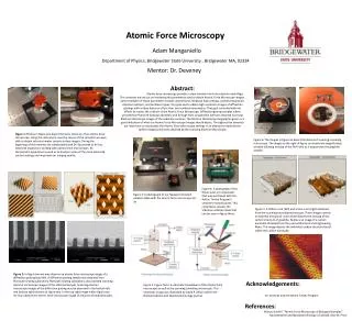
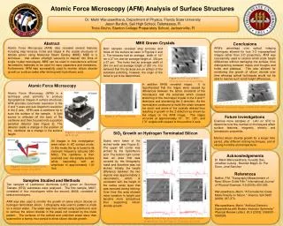
Atomic Force Microscope (AFM) • Introduction • The atomic force microscope (AFM) was invented in1986 by Binnig, Quate and Gerber. • The AFM raster scans a sharp probe over the surface of a sample and measures the changes in force between the probe tip and the sample.
Working Concept • The physical parameter probed is a force resulting from different interactions. • Thus, an AFM image is generated by recording the force changes as the probe (or sample) is scanned in the x and y directions. • The sample is mounted on a piezoelectric scanner, which ensures three-dimensional positioning with high resolution. • The force is monitored by attaching the probe to a pliable cantilever, which acts as a spring, and measuring the bending or "deflection" of the cantilever.
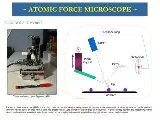
Principle • The AFM consists of a cantilever with a sharp tip (probe) at its end that is used to scan the specimen surface. • The cantilever is typically silicon or silicon nitride with a tip radius of curvature on the order of nanometers. • When the tip is brought into proximity of a sample surface, forces between the tip and the sample lead to a deflection of the cantilever according to Hooke's law. • Depending on the situation, forces that are measured in AFM include mechanical contact force, van der Waals forces, capillary forces, chemical bonding, electrostatic forces.
Basic set-up of an AFM • The ability of an AFM to achieve near atomic scale resolution depends on the three essential components: • (1) a cantilever with a sharp tip, • (2) a scanner that controls the x-y-z position, and • (3) the feedback control and loop.
Cantiliever with a sharp tip. The stiffness of the cantilever needs to be less the effective spring constant holding atoms together, which is on the order of 1 - 10 nm. • The tip should have a radius of curvature less than 20-50 nm (smaller is better) a cone angle between 10-20 degrees. • 2. Scanner. The movement of the tip in the sample in the x, y, and z-directions is controlled by a piezo-electric tube scanner. • For typical AFM scanners, the maximum ranges for are 80 mm x 80 mm in the x-y plane and 5 mm for the z-direction.
3. Feedback control.The forces that are exerted between the tip and the sample are measured by the amount of bending (or deflection) of the cantilever. • By calculating the difference signal in the photodiode quadrants, the amount of deflection can be correlated with a height . • Because the cantilever obeys Hooke's Law for small displacements, the interaction force between the tip and the sample can be determined.
Imaging Modes • Contact Mode • Tapping Mode • Non contact Mode
Contact mode • The tip is "dragged" across the surface of the sample and the contours of the surface are measured either using the deflection of the cantilever directly or, more commonly, using the feedback signal required to keep the cantilever at a constant position. • Because the measurement of a static signal is prone to noise and drift, low stiffness cantilevers are used to achieve a large enough deflection signal while keeping the interaction force low. • Thus, contact mode AFM is almost always done at a depth where the overall force is repulsive, that is, in firm "contact" with the solid surface.
Tapping mode • The cantilever is driven to oscillate up and down at or near its resonance frequency. • The amplitude of this oscillation usually varies from several nm to 200 nm. • The interaction of forces acting on the cantilever when the tip comes close to the surface, Van der Waals forces, dipole-dipole interactions, electrostatic forces, etc. • This causes the amplitude of the cantilever's oscillation to change (usually decrease) as the tip gets closer to the sample. • This amplitude is used as the parameter that goes into the electronic servo that controls the height of the cantilever above the sample. • A tapping AFM image is therefore produced by imaging the force of the intermittent contacts of the tip with the sample surface.
Non contact method • In non-contact mode, the tip of the cantilever does not contact the sample surface. • The cantilever is instead oscillated at either its resonant frequency or just above (amplitude modulation) where the amplitude of oscillation is typically a few nanometers (<10 nm) down to a few picometers. • The van der Waals forces, which are strongest from 1 nm to 10 nm above the surface acts to decrease the resonance frequency of the cantilever. • Measuring the tip-to-sample distance at each (x,y) data point allows the scanning software to construct a topographic image of the sample surface. • Non-contact mode AFM does not suffer from tip or sample degradation effects that are sometimes observed after taking numerous scans with contact AFM. This makes non-contact AFM preferable to contact AFM for measuring soft samples, e.g. biological samples and organic thin film.
Applications • The AFM is useful for obtaining three-dimensional topographic information of insulating and conducting structures with lateral resolution down to 1.5 nm and vertical resolution down to 0.05 nm. • These samples include clusters of atoms and molecules, individual macromolecules, and biologic al species (cells, DNA, proteins). • Minimal sample preparation involved for AFM imaging. • The AFM can operate in gas, ambient, and fluid environments and can measure physical properties including elasticity, adhesion, hardness, friction and chemical functionality.
Advantages • The AFM has several advantages over the scanning electron microscope (SEM). • Unlike the electron microscope which provides a two-dimensional projection or a two-dimensional image of a sample, the AFM provides a true three-dimensional surface profile. • Additionally, samples viewed by AFM do not require any special treatments (such as metal/carbon coatings) that would irreversibly change or damage the sample.
While an electron microscope needs an expensive vacuum environment for proper operation, most AFM modes can work perfectly well in ambient air or even a liquid environment. • This makes it possible to study biological macromolecules and even living organisms. • In principle, AFM can provide higher resolution than SEM.
Disadvantages • A disadvantage of AFM compared with the scanning electron microscope (SEM) is the image size. • The SEM can image an area on the order of millimetres by millimetres with a depth of field on the order of millimetres. • The AFM can only image a maximum height on the order of micrometres and a maximum scanning area of around 150 by 150 micrometres. • Another inconvenience is that at high resolution, the quality of an image is limited by the radius of curvature of the probe tip, and an incorrect choice of tip for the required resolution can lead to image artifacts.