Download
1 / 47
510 likes | 617 Views
Explore sequential logic design with insights on storage mechanisms like positive feedback and charge-based setups. Learn naming conventions for latches and registers, including flip-flops and dual-edge designs. Dive into latch-based systems, timing definitions, feedback mechanisms, and clocking schemes.

E N D
Designing SequentialLogic Circuits Jan M. Rabaey Anantha Chandrakasan Borivoje Nikolic
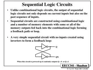
Inputs Outputs Combinational Logic State Next State Current State Clock Sequential Logic 2 storage mechanisms: • positive feedback • charge-based
Naming Conventions • In the text: • a latch is level sensitive • a register is edge-triggered • Many different naming conventions: • flip-flops (level or edge?) • Transparency? • Dual edge/level
Latch versus Register • Register- stores if clock rises, never transparent (mostly) • Latch- stores if clock is low transparent if clock is high D Q D Q Clk Clk Clk Clk D D Q Q
Latch-Based Design • N latch is transparentwhen f = 0 • P latch is transparent when f = 1 f N P Logic Latch Latch Logic
Timing Definitions CLK Register t D Q t t setup hold D DATA CLK STABLE t t c lk2q Q DATA STABLE t
Maximum Clock Frequency f Timing Constraints: tclk2q + tp(comb) + tsetup = T tcdreg + tcdlogic > thold First Constraint ensures clock is slow enough that Registers sample correct value Second Constraint ensures that there is no path after the clock changes to alter the previously stored data Register LOGIC t P(comb)
V V Vi2 V i o1 1 o 2 A C B V V = = V V i i 1 2 o o 1 2 Positive Feedback: Bi-Stability 1 1 o o V V 5 2 i V A,B Stable points C is unstable:(metastable) Feedback moves state to Stable points, eventually 1 o V 5 2 i V V V = V V V = V i i 1 o 2 o 2 1 o 1 2 i
CLK D D CLK Writing a Static Latch Use the clock to distinguish between the transparent and opaque states Forcing the state (can implement as NMOS-only) Converting into a MUX
Q 0 D 1 Q 1 D 0 CLK Mux-Based Latches Negative latch (transparent when CLK= 0) Positive latch (transparent when CLK= 1) CLK
Master-Slave Register CLK D Qm Qm Q D Q CLK CLK Two opposite latches trigger on edge Also called master-slave latch pair
D Tclk-q Tclk-q CLK Q Clk-Q Delay Clock to Q delays are Different for rising and falling Transitions Use Worst Case – not Avg!
Setup Time (MS register) Q Qm Q D D Qm CLK Setup = 0.20nS Failed to pass D Setup = 0.21nS Passed D
Cross-Coupled Pairs NOR-based set-reset Q’ Q’ 0 1 - Q Q 1 0 - R 0 0 1 1 S 0 1 0 1 S Q R Q’
Added clock Cross-coupled NANDs This is not used in datapaths any more,but is a basic register memory cell Cross-Coupled NAND
Sizing Issues 2 W=0.5 1 Q’ (V) W=0.7 W=0.8 2.5 3.5 0 1 3.0 2 W=1 W/L (M5,M6) M2=6 Output voltage dependence on transistor width Transient response
Storage Mechanisms Dynamic (charge-based) Static CLK D Q CLK
Setup/Hold Time Illustrations Circuit before clock arrival (Setup-1 case)
Setup/Hold Time Illustrations Circuit before clock arrival (Setup-1 case)
Setup/Hold Time Illustrations Circuit before clock arrival (Setup-1 case)
Setup/Hold Time Illustrations Circuit before clock arrival (Setup-1 case)
Setup/Hold Time Illustrations Circuit before clock arrival (Setup-1 case)
Setup/Hold Time Illustrations Hold-1 case 0
Setup/Hold Time Illustrations Hold-1 case 0
Setup/Hold Time Illustrations Hold-1 case 0
Setup/Hold Time Illustrations Hold-1 case 0
Setup/Hold Time Illustrations Hold-1 case 0
Other Latches/Registers: C2MOS “Keepers” can be added to make circuit pseudo-static
Insensitive to Clock-Overlap V V V V DD DD DD DD M M M M 2 6 2 6 M M 0 0 4 8 X X D Q D Q M M 1 1 3 7 M M M M 1 5 1 5 (a) (0-0) overlap (b) (1-1) overlap
Pipelined Reference Pipelining
Positive latch (transparent when CLK= 1) Negative latch (transparent when CLK= 0) Other Latches/Registers: TSPC
Pulse-Triggered LatchesAn Alternative Approach Ways to design an edge-triggered sequential cell: Master-Slave Latches Pulse-Triggered Latch L1 L2 L Data Data D Q D Q D Q Clk Clk Clk Clk Clk
Latch-Based Pipeline ~CLK CLK CLK F G F G
Non-Bistable Sequential Circuits─Schmitt Trigger • VTC with hysteresis • Restores signal slopes
CMOS Schmitt Trigger Moves switching threshold of the first inverter
Schmitt Trigger Simulated VTC 2.5 2.5 2.0 2.0 V 1.5 1.5 M 1 (V) (V) x X 1.0 1.0 V V V M 2 k = 1 k = 3 k = 2 0.5 0.5 k = 4 0.0 0.0 0.0 0.5 1.0 1.5 2.0 2.5 0.0 0.5 1.0 1.5 2.0 2.5 V (V) V (V) in in Voltage-transfer characteristics with hysteresis. The effect of varying the ratio of the PMOS device M . The width is k * 0.5 m. m 4
Ring Oscillator 0 1 2 N-1 simulated response of 5-stage oscillator Astable Multivibrators (Oscillators)
V V 2 1 o o in 2 in 1 v 3 v 1 v 2 v 4 V ctrl delay cell 3.0 V V V V 1 2 3 4 2.5 2.0 1.5 1.0 0.5 0.0 0.5 2 0.5 1.5 2.5 3.5 time (ns) Differential Delay Element and VCO two stage VCO simulated waveforms of 2-stage VCO
Homework 7 • A common way to characterize registers is to measure the timing aperture which is the total window in which transitions on data are not correctly output. This is done by making two clocks which are close, but not the same so that the relative phase drifts slowly with each cycle. Construct a pseudo-static master/slave flip-flop in SUE with the assumption that the input is driven by a unit inverter (2/1, min width nmos), the clock is driven by a 2x inverter. Optimize your designs to minimize the timing aperture (setup+hold) and clock to Q assuming the output load is 2 min inverters. Simulate your designs in SPICE and turn in both the designs (annotated schematics and spice results – plz. don’t waste paper!) • Do problem 1 again, with TSPC based flipflop. (High performance)