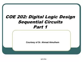
Exploring Basic Sequential Circuits in Verilog: Latches, Flip-Flops, Registers, and More
This lecture delves into the fundamental concepts of basic sequential circuits using Verilog, covering latches, flip-flops, registers, counters, shift registers, datapaths, and state machines. We explore the R-S Latch operation, detailing both active HIGH and active LOW configurations. The lecture emphasizes Verilog coding techniques for implementing these circuits, including example modules for D flip-flops, counters, and shift registers. By understanding these basic building blocks, students can design and simulate more complex digital systems effectively.

Exploring Basic Sequential Circuits in Verilog: Latches, Flip-Flops, Registers, and More
E N D
Presentation Transcript
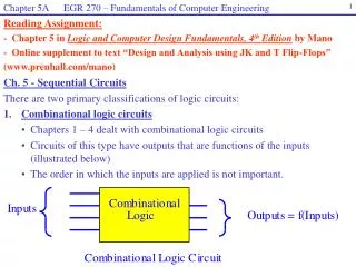
Logic Design Review – 3Basic Sequential Circuits Lecture L14.3 Verilog
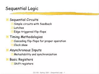
Basic Sequential Circuits • Latches • Flip-Flops • Registers • Counters • Shift Registers • Datapaths • State Machines
R-S Latch R Q S R-S Latch Q is set to 1 when S is asserted, and remains unchanged when S is disasserted. Q is reset to 0 when R is asserted, and remains unchanged when R is disasserted. Assertions can be active HIGH or active LOW
R-S Latch R Q S module RSlatch ( Q ,R ,S ); input R ; wire R ; input S ; wire S ; output Q ; reg Q ; always @(R or S) begin if(S == 1 && R == 0) Q = 1; elseif(S == 0 && R == 1) Q = 0; end endmodule Active HIGH
R-S Latch R Q S module RSlatch ( Q ,R ,S ); input R ; wire R ; input S ; wire S ; output Q ; reg Q ; always @(R or S) begin if(S == 0 && R == 1) Q = 1; elseif(S == 1 && R == 0) Q = 0; end endmodule Active LOW
Note that this is different from the "textbook" RS latch module RSlatchNOR ( Q ,R ,S ); input R ; wire R ; input S ; wire S ; output Q ; wire Q ; wire F1, F2; nor #10 (F1,F2,R); nor #10 (F2,F1,S); assign Q = F1; endmodule 10ns propagation delay
R S Q 0 0 Q0 store 0 1 1 set 1 0 0 reset 1 1 0 disallowed
R-S Latch R Q S How can you make this R-S latch from gates? Q is set to 1 when S is asserted, and remains unchanged when S is disasserted. Q is reset to 0 when R is asserted, and remains unchanged when R is disasserted. Assertions can be active HIGH or active LOW
SQ R-S Latch 00 01 11 10 R R Q 0 S 1 Q is set to 1 when S is asserted (1), and remains unchanged when S is disasserted (0). Q is reset to 0 when R is asserted (1), and remains unchanged when R is disasserted (0). R S Q Q 0 0 0 0 0 0 1 1 0 1 0 1 0 1 1 1 1 0 0 0 1 0 1 0 1 1 0 0 1 1 1 1 store 1 1 1 set 1 reset store Q = ~R & Q | ~R & S | S & Q
R-S Latch R Q S RS Latch R S Q Q 0 0 0 0 0 0 1 1 0 1 0 1 0 1 1 1 1 0 0 0 1 0 1 0 1 1 0 0 1 1 1 1 store set reset store Q = ~R & Q | ~R & S | S & Q
module RSlatchGates ( Q ,R ,S ); input R ; wire R ; input S ; wire S ; output Q ; wire Q ; assign #10 Q = ~R & Q | ~R & S | S & Q; endmodule
D Latch D Q EN D Latch Q follows D when EN is high, and remains unchanged when EN is low..
D Latch D Q EN module Dlatch ( Q ,EN ,D ); input EN ; wire EN ; input D ; wire D ; output Q ; reg Q ; always @(D or EN) if(EN == 1) Q = D; endmodule
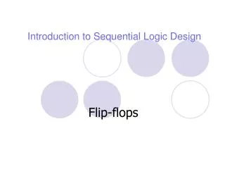
Basic Sequential Circuits • Latches • Flip-Flops • Registers • Counters • Shift Registers • Datapaths • State Machines
Q D clk !Q D clk Q !Q 0 0 1 1 1 0 X 0 Q0 !Q0 D Flip-Flop Positive edge triggered D gets latched to Q on the rising edge of the clock. Behavior always @(posedge clk) Q <= D;
Q D clk !Q DFF.v module DFF (D, clk, Q, notQ ); input clk ; wire clk ; input D ; wire D ; output Q ; reg Q ; output notQ ; wire notQ ; always @(posedge clk) Q <= D; assign notQ = ~Q; endmodule Note non-blocking assignment
DFFclr.v module DFFclr (D, clk, clr, Q, notQ ); input clk ; wire clk ; input clr ; wire clr ; input D ; wire D ; output Q ; reg Q ; output notQ ; wire notQ ; always @(posedge clk orposedge clr) if(clr == 1) Q <= 0; else Q <= D; assign notQ = ~Q; endmodule Asynchronous clear
Basic Sequential Circuits • Latches • Flip-Flops • Registers • Counters • Shift Registers • Datapaths • State Machines
A 1-Bit Register Behavior always @(posedge clk) if(LOAD == 1) Q0 <= INP0;
A Generic Register // An n-bit register with asynchronous clear and load module register(clk,clr,load,d,q); parameter n = 8; input [n-1:0] d; input clk,clr,load; output [n-1:0] q; reg [n-1:0] q; always @(posedge clk orposedge clr) if(clr == 1) q <= 0; elseif(load) q <= d; endmodule
Basic Sequential Circuits • Latches • Flip-Flops • Registers • Counters • Shift Registers • Datapaths • State Machines
count3 clr Q(2 downto 0) clk 3-Bit Counter Behavior always @(posedge clk orposedge clr) begin if(clr == 1) Q <= 0; else Q <= Q + 1; end
counter3.v module counter3 (clk, clr, Q ); input clr ; wire clr ; input clk ; wire clk ; output [2:0] Q ; reg [2:0] Q ; // 3-bit counter always @(posedge clk orposedge clr) begin if(clr == 1) Q <= 0; else Q <= Q + 1; end endmodule Asynchronous clear Output count increments on rising edge of clk
Clock 4.0 MHz Q0 2.0 MHz Q1 1.0 MHz Q2 0.5 MHz Q3 0.25 MHz Clock Divider Clk4 = 4 MHz clock
Basic Sequential Circuits • Latches • Flip-Flops • Registers • Counters • Shift Registers • Datapaths • State Machines
shift4.v module ShiftReg(clk,clr,data_in,Q); input clk; input clr; input data_in; output [3:0] Q; reg [3:0] Q; // 4-bit Shift Register always @(posedge clk orposedge clr) begin if(clr == 1) Q <= 0; else begin Q[3] <= data_in; Q[2:0] <= Q[3:1]; end end endmodule Note non-blocking assignment
ring4.v module ring4(clk,clr,Q); input clk; input clr; output [3:0] Q; reg [3:0] Q; // 4-bit Ring Counter always @(posedge clk orposedge clr) begin if(clr == 1) Q <= 1; else begin Q[3] <= Q[0]; Q[2:0] <= Q[3:1]; end end endmodule
johnson4.v module johnson4(clk,clr,Q); input clk; input clr; output [3:0] Q; reg [3:0] Q; // 4-bit Johnson Counter always @(posedge clk orposedge clr) begin if(clr == 1) Q <= 0; else begin Q[3] <= ~Q[0]; Q[2:0] <= Q[3:1]; end end endmodule
Q3 Q2 Q1 Q0 0 0 0 1 1 1 0 0 0 8 1 1 0 0 C 1 1 1 0 E 1 1 1 1 F 0 1 1 1 7 1 0 1 1 B 0 1 0 1 5 Q3 Q2 Q1 Q0 1 0 1 0 A 1 1 0 1 D 0 1 1 0 6 0 0 1 1 3 1 0 0 1 9 0 1 0 0 4 0 0 1 0 2 0 0 0 1 1
rand4.v module rand4(clk,clr,Q); input clk; input clr; output [3:0] Q; reg [3:0] Q; // 4-bit Random number generator always @(posedge clk orposedge clr) begin if(clr == 1) Q <= 1; else begin Q[3] <= Q[3] ^ Q[0]; Q[2:0] <= Q[3:1]; end end endmodule
outp inp Q2 Q1 Q0 clk Clock Pulse
clk_pulse.v module clk_pulse(clk,clr,inp,outp); input clk; input clr; input inp; output outp; wire outp; reg [2:0] Q; // clock pulse generator always @(posedge clk orposedge clr) begin if(clr == 1) Q <= 0; else begin Q[2] <= inp; Q[1:0] <= Q[2:1]; end end assign outp = Q[2] & Q[1] & ~Q[0]; endmodule
outp inp Q2 Q1 Q0 clk