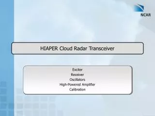
HIAPER Cloud Radar Transceiver
190 likes | 357 Views
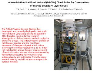
HIAPER Cloud Radar Transceiver. Exciter Receiver Oscillators High-Powered Amplifier Calibration. Overview. Exciter Receiver Oscillators High-Powered Amplifier Calibration. Exciter: Requirements. 200 ns to 2 µs transmitted pulse (Phase A) Requires 5 MHz linear-phase bandwidth

HIAPER Cloud Radar Transceiver
E N D
Presentation Transcript
HIAPER Cloud Radar Transceiver Exciter Receiver Oscillators High-Powered Amplifier Calibration
Overview • Exciter • Receiver • Oscillators • High-Powered Amplifier • Calibration
Exciter: Requirements • 200 ns to 2 µs transmitted pulse (Phase A) • Requires 5 MHz linear-phase bandwidth • Accommodate extension to a pulse compression waveform (Phase B system) such as an amplitude tapered linear FM or non-linear FM • Require arbitrary phase and amplitude control within generated pulse • Design for 20 MHz of linear-phase bandwidth in order to shape the spectrum of the transmitted pulse
Exciter: Waveform Generator • Baseband I and Q samples used to generate a Hilbert transform pair of signals centered at 125 MHz • Images at 375 MHz (using 500 MS/s DAC) will be suppressed by 70 dB • Allows for amplitude and phase control to shape the transmitted spectrum
Exciter: 1.3 GHz Up-Conversion • Up-conversion to 1.3 GHz using a quadrature modulator • Lower sideband is suppressed by > 20 dB
Exciter: Single Sideband Generation m(t) • m(t) and mh(t) form a Hilbert transform pair centered in frequency at 125 MHz • Output of the quadrature modulator is a single sideband signal (the lower sideband at 1050 MHz is suppressed) mh(t)
Exciter: 1.3 GHz Filtering • Filter signal at 1.3 GHz to further suppress lower sideband by 40 dB (min.) • Filter has a 20 MHz, linear phase passband
Exciter: 94 GHz Up-Conversion • Up-convert 1.3 GHz signal to 94 GHz using a single sideband modulator • Lower sideband signal at 91.4 GHz is suppressed by 20 dB
Exciter: 94 GHz Filtering • Filter 94 GHz signal to further suppress lower sideband at 91.4 GHz by 26 dB • Transmitter will further suppress image due to limited bandwidth (~100 MHz)
Overview • Exciter • Receiver • Oscillators • High-Powered Amplifier • Calibration
Receiver: Requirements • Receiver Requirements • 5 MHz linear phase bandwidth (Phase A) • Accommodate extension to a pulse compression waveform (Phase B system) • Desire 20 MHz of linear phase bandwidth • Non-polarimetric receiver (Phase A) that should be upgradeable to a fully-polarimetric receiver in Phase B
Receiver: T/R Isolation • Receiver must be protected from the reflected transmit signal from the antenna • For an antenna with a 14 dB return loss (1.5:1 VSWR), an a peak incident power of 60.7 dBm at the antenna terminals, the signal at the input to the latching circulators is 45.4 dBm • For a LNA max. input power of +20 dBm, T/R isolation required is 42 dB (2 latching circulators @ 25 dB each)
Receiver: 94 GHz Filtering • Image rejection filter suppresses received signals at the image frequency by > 46 dB
Receiver: 94 GHz Down-Conversion • Received signal is down-converted to 1.3 GHz • If suppression of image at 91.4 GHz is not sufficient, then an image reject mixer will be used
Receiver: 1.3 GHz Filtering • Received signal is filtered which suppresses signals in lower sideband by > 40 dB (> 100 dB rejection)
Receiver: 1.3 GHz Down-Conversion • Received signal is down-converted to 125 MHz • The 5 MHz anti-aliasing filter will be changed for Phase B
Receiver: Performance • Receiver performance was calculated using commercially available components • Noise figure • Receiver noise figure 9.35 dB (noise power in 5 MHz BW is −97.9 dBm) • Dynamic range • Maximum input signal to the receiver is −22.4 dBm • Dynamic range is −22.4 − (−97.9) = 75.5 dB • 14 bit ADC required to capture receiver dynamic range • Intermodulation products will be analyzed during component selection
Overview • Exciter • Receiver • Oscillators • High-Powered Amplifier • Calibration
Oscillators: Phase Noise • Phase noise analysis performed on W-band local oscillator using data in the table below to determine phase noise requirements • Velocity variance due to phase noise for an echo at 10 km is 0.07 m/s