Motors
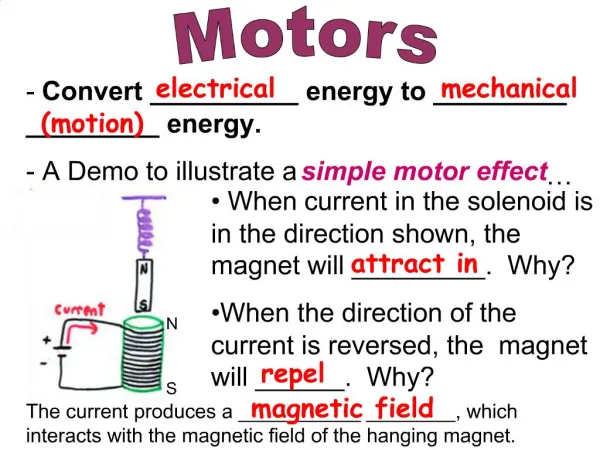
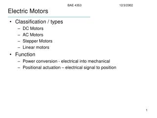
Motors. Lucas Bazile. What is a Motor. A motor is an electrical machine that converts electrical energy into mechanical energy

Motors
E N D
Presentation Transcript
Motors Lucas Bazile
What is a Motor • A motor is an electrical machine that converts electrical energy into mechanical energy • There are both DC and AC motors. A DC motor converts direct current electrical energy into mechanical energy and an AC motor converts alternating current electrical energy into mechanical energy
DC motors • DC Motors utilize the properties of magnetism to convert electrical energy to mechanical energy • When current passes through a conductor it generates an electromagnetic field which can interact with other magnetic fields. When magnetic fields interact a force is generated depending on the strength of each field, their distance, and their polar orientation.
Permanent magnet dc motors • In a permanent magnet dc motor, mechanical rotation is attained through interaction of a permanent magnet’s magnetic field and the magnetic field of a conductor with current running through it. • The permanent magnet is kept stationary in a part of the motor called the stator, while the current carrying conductor will be allowed to rotate as its magnetic field interacts with the magnetic field of the stator. The rotating part of the motor is called the rotor
Dc motors (continued) By configuring the motor in such a way that the current carrying conductor is able to rotate freely, mechanical motion can be generated by applying a current. The current will create a magnetic field which will interact with the magnetic field of the permanent magnet. This creates a force, and since the armature is able to move, this force will act on the armature (which is part of the rotor) causing it to rotate. In order for the motor to work, the armature must both be able to rotate freely and have a constant connection to a dc source. This is done by applying voltage via carbon brushes. The brushes are pushed against the commutator (with the help of springs) allowing the brushes to remain in a fixed position even as the armature begins to rotate due the magnetic field being generated from the current running through the armature.
Dc motors (continued) • The commutator is designed in such a way that as the armature rotates, the dc voltage applied by the brushes will alternate, which switches the direction of the current through the armature. This is good because since the armature itself has rotated, the magnetic field will have changed its orientation. By also alternating the applied voltage as the armature rotates we are able to control the orientation of the magnetic field of the armature to ensure that the largest possible force is acting on the armature regardless of its physical orientation. As the armatures rotates against the brushes, the brushes will eventually grind down and need to be changed.
Dc motors (continued) Because the polar orientation of the magnetic fields in a motor are not constant, there is a varying force exerted on the armature, resulting in a choppy rotation. The change in force is due to the armature cutting through less flux lines from the magnetic field of the stator when the armature is oriented perpendicular to the flux lines. To help combat this, additional commutator terminals that are connected to conductors are added at angles. The more coils at varying angles means more positions in the armatures rotation in which conductors will be perpendicular to the flux lines of the stator’s magnetic field, which is when force exerted on the armature is at maximum. This allows smoother motion and more consistent torque.
Dc Shunt motor • A DC shunt motor works much the same way as a permanent magnet motor. The difference is that the stator will create an electromagnetic field rather than use permanent magnets to create a magnetic field. • The coil used to create the electromagnetic field (called the field winding) is connected in parallel to the armature winding (this is called shunting). • The current to the field winding and the armature winding are supplied from the same power supply. • DC shunt motors have efficient speed regulation.
Series wound dc motor • The series wound dc motor also uses a field winding to create an electromagnetic field • The field winding is connected in series with the armature winding. • The field winding of a series motor will experience much more current than the field winding of a shunt motor. • Series wound motors have high starting torque.
Compound wound dc motor • A compound wound dc motor uses field coils attached both in series and in parallel to the armature coils. • Created to achieve the benefits of both shunt and series motors. • These motors don’t achieve the starting torque of series motors or the efficiency in speed control of shunt motors but they have a better balance of the strength between the two types of motors.
Brushless dc motor • Brushless dc motors are similar to permanent magnet motors but they do not require the use of brushes to operate. • The permanent magnets make up the rotor rather than the stator and the electromagnetic field is generated in the stator. • Through clever circuitry, we can pass current through only certain parts of the field coils which will create a rotating magnetic field which will act on the magnetic field of the permanent magnets.
Brushless dc motors (continued) • Because no brushes are used, the operation of the brushless dc motors are much more quiet and more efficient because less energy is lost through mechanical operation (such as friction between the brushes and the commutator).
More Complex DC Motors The strength of the interacting magnetic fields determines the strength of the force that will act on the armature. The amount of flux lines interacting determines the force acting on the armature. In cases with permanent magnets in the stator, only the amount of flux lines in the armature can be controlled. You can increase the flux density by either increasing the current through the armature’s windings or by adding another conductor. This often means to get the most out of smaller dc motors, the current carrying conductor is wrapped a number of times (increasing the total length of conductor in small volume). We refer to each section of wrapped conductor as a coil.
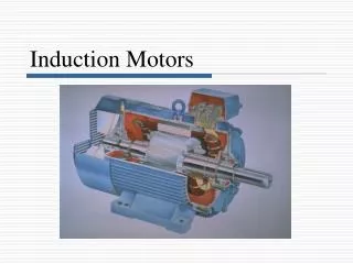
AC Motors • Ac motors use the property of induction to transfer electrical energy into mechanical energy. Both the stator and the rotor will be electromagnets. • When an ac signal is sent into the stator of the motor, an alternating magnetic field is generated. Current is induced in conductors when there is relative motion between a magnetic field and a conductor. So the alternating magnetic field will induce a current in the conductor of the rotor. The current induced in the rotor will then create its own magnetic field which will interact with the alternating magnetic field of the stator. Now that there are two magnetic fields with relative motion, forces will be applied.
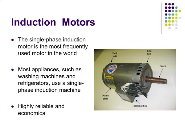
Asynchronous ac motors • Also known as induction motors because they induce a current in the rotor which causes an electromagnetic field. • Known as asynchronous because the rotor will never reach the speed of the rotating magnetic field of the stator (known as synchronous speed). • 2 types of induction motors: single-phase and 3-phase
Single-phase ac motor • Single-phase ac motors operate using one phase of ac current. • By running this current through a winding in the stator, a pulsating (non-rotating) magnetic field is created. Because there is relative motion between this pulsating magnetic field and the rotor windings, a current is induced. • The current induced in the rotor creates a pulsating magnetic field as well, and this magnetic field interacts with the field from the stator.
Single-phase ac motors (continued) • When the rotor is stationary, the magnetic field induced in the rotor will be equal in magnitude but opposite the magnetic field in the stator. This means that there will be no net torque that will force the rotor to rotate, meaning that single-phase motors are not self-starting, they need an initial rotation in order to continue rotating. • If the rotor is already rotating however, there will be a net torque which will force to the rotor to continue rotating. • A number of different solution were created to create self-starting single-phase motors.
Types of single-phase motors • Split phase • Shaded pole • Capacitor start & Capacitor start capacitor run
Split phase motor • In a split phase motor, an additional field winding is added that will only be part of the circuit during motor startup. • This additional winding (called the starting or auxiliary winding) is made to have a much higher resistance than the main or running winding.
Split phase motor (continued) • Because a highly resistive winding has current in phase with supply voltage, and highly conductive winding has current more out of phase with supply voltage, the two windings will create a magnetic field out of phase with each other from just a single ac signal • These two pulsating out of phase magnetic fields will create a single rotating magnetic field, which will allow a net torque to be applied to the rotor even when at rest. • The auxiliary winding is attached to the circuit via a centrifugal switch which will disconnect once the motor reaches a certain speed, switching the magnetic field back to a non-rotating pulsating magnetic field.
Shaded pole ac motor • In a shaded pole motor, protruding poles are added to the stator. A small portion of the pole is covered (shaded) by some inductive material such as copper. • When an ac signal is sent to the stator, an alternating magnetic field is generated. This field induces a current in the shaded poles opposite to the direction of the field windings, which creates a magnetic field opposite to the stator field.
Shaded pole ac motor (continued) • The effect of the magnetic field in the shaded poles is enough to create a slight rotating magnetic field in the stator which will cause the rotor to begin rotating. • This method produces very low starting torque but is more reliable and robust because it does not rely on a mechanical centrifugal switch
Capacitor start motor • Capacitor start motors use similar idea to split phase motors. • A current with a phase difference is run through an auxiliary winding to create a rotating magnetic field rather than a pulsating magnetic field. • A capacitor is used rather than resistance to achieve the phase difference in this motor • The phase difference between the two field windings in this motor is much greater (close to 90 degrees) than in the split phase motor so the starting torque is higher.
Capacitor start motor (continued) • A centrifugal switch can be used to disconnect the auxiliary winding however, some motors will keep the auxiliary winding running connected throughout motor use. These are called capacitor start/run motors. • Single phase capacitor start/run motors will have less startup torque and less speed than capacitor start motors.
Properties • Single-phase motors are not inherently self starting. • Typically used in low power house-hold applications. • Long lasting and durable.
3-phase ac motor • 3 phase AC motors use 3 ac signals to operate • Because they use 3 signals a rotating magnetic field is generated without any need for special care.
Synchronous ac motor • Synchronous motors are ac motors in which the rotor will rotate at the same speed as the rotating magnetic field of the stator. • Uses both 3 phases of ac current and a dc current to operate • Are not inherently self starting • Can only operate at synchronous speed
PSpice lacks the ability to directly represent mechanical properties, so in order to represent a motor in multisim, circuits that emulate the mathematical relationships between the mechanical properties and the electrical properties of a motor will be used.
Electrical Circuit • The base electrical circuit will consist of a voltage source, inductor, resistor, and a current controlled voltage source. • The voltage source will be used as power supply • The current controlled voltage source will be used to represent the back_emf (a ccvs must be used because its value is dependent on the current that will be obtained from the mechanical circuit equivalent) • The resistor will be used to represent the resistor of the coils in the armature • The inductor represents the induction of the coils
Mechanical Circuit Equivalent • The mechanical circuit will contain the following multisim components to represent mechanical properties
Relationships • The speed at which the motor shaft rotates is represented by the current in the mechanical circuit. This allows to use the ccvs from our electrical circuit and connect it to the mechanical circuit to properly represent the back_emf as it too is dependent on the speed of rotation of the motor shaft (current of mechanical circuit) • The torque the motor will apply is dependent on a special value called the “torque constant” and the current flowing through the electrical circuit. This is represented using a ccvs connected to the electrical circuit.
Goal • To create a dynamometer based of the design from http://www.instructables.com/id/RC-Motor-Dynamometer-V10/ • Test and measure small dc motors
Outline of Dyno • The dyno case will be 3d printed • An Arduino Uno will be used to control current to the motor and the take the readings from a sensor. The Arduino will calculate rpm from data from sensor • Dyno will be used to measure small dc motors
Circuit Parts List • 1 IRL7833 MOSFET • 1 TCRT1000 Optical Sensor • 1 100 Ohm Resistor • 1 1k Ohm Resistor • 1 4.65k Ohm Resistor • 1 100k Ohm Resistor • Arduino Uno • Arduino Uno prototype shield
Parts for Housing • Hot glue gun • 3d printed wheel • 3d printed Arduino housing • 3d printed motor housing • 3d printed sensor arm • Electrical tape
Analyzing The Data • The dyno is able to calculate the rpm at certain time intervals for us, now we can use excel to observe the polynomial that describes to motors behavior and calculus to calculate the torque and power.