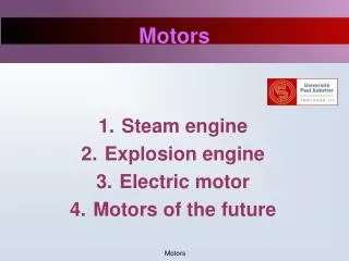
Motors
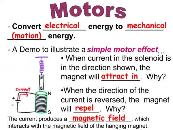
Motors. Sean DeHart Smriti Chopra Hannes Daepp . Overview. DC Motors (Brushed and Brushless) Brief Introduction to AC Motors Stepper Motors Linear Motors. 2. Sean DeHart. Electric Motor Basic Principles. Interaction between magnetic field and current carrying wire produces a force


Motors
E N D
Presentation Transcript
Motors Sean DeHart Smriti Chopra Hannes Daepp
Overview • DC Motors (Brushed and Brushless) • Brief Introduction to AC Motors • Stepper Motors • Linear Motors 2 Sean DeHart
Electric Motor Basic Principles • Interaction between magnetic field and current carrying wire produces a force • Opposite of a generator 3 Sean DeHart
Conventional (Brushed) DC Motors • Permanent magnets for outer stator • Rotating coils for inner rotor • Commutation performed with metal contact brushes and contacts designed to reverse the polarity of the rotor as it reaches horizontal 4 Sean DeHart
2 pole brushed DC motor commutation 5 Sean DeHart
Conventional (Brushed) DC Motors • Common Applications: • Small/cheap devices such as toys, electric tooth brushes, small drills • Lab 3 • Pros: • Cheap, simple • Easy to control - speed is governed by the voltage and torque by the current through the armature • Cons: • Mechanical brushes - electrical noise, arcing, sparking, friction, wear, inefficient, shorting 6 Sean DeHart
DC Motor considerations • Back EMF - every motor is also a generator • More current = more torque; more voltage = more speed • Load, torque, speed characteristics • Shunt-wound, series-wound (aka universal motor), compound DC motors 7 Sean DeHart
Brushless DC Motors • Essential difference - commutation is performed electronically with controller rather than mechanically with brushes 8 Sean DeHart
Brushless DC Motor Commutation • Commutation is performed electronically using a controller (e.g. HCS12 or logic circuit) • Similarity with stepper motor, but with less # poles • Needs rotor positional closed loop feedback: hall effect sensors, back EMF, photo transistors 9 Sean DeHart
BLDC (3-Pole) Motor Connections • Has 3 leads instead of 2 like brushed DC • Delta (greater speed) and Wye (greater torque) stator windings Delta Wye 10 Sean DeHart
Brushless DC Motors • Applications • CPU cooling fans • CD/DVD Players • Electric automobiles • Pros (compared to brushed DC) • Higher efficiency • Longer lifespan, low maintenance • Clean, fast, no sparking/issues with brushed contacts • Cons • Higher cost • More complex circuitry and requires a controller 11 Sean DeHart
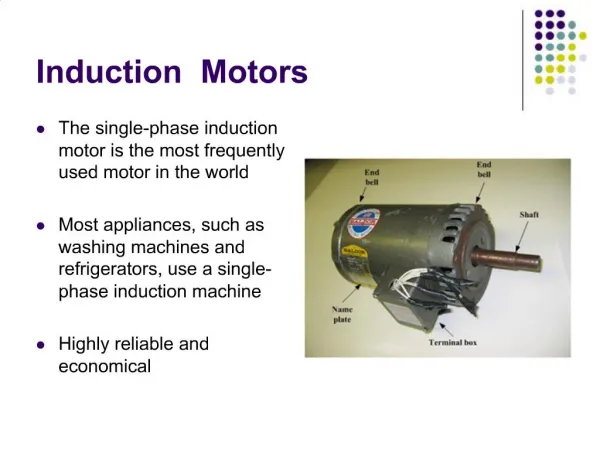
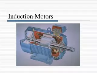
AC Motors Two main types of AC motor, Synchronous and Induction. Synchronous motors supply power to both the rotor and the stator, where induction motors only supply power to the stator coils, and rely on induction to generate torque. 12 Sean DeHart
AC Induction Motors (3 Phase) • Use poly-phase (usually 3) AC current to create a rotating magnetic field on the stator • This induces a magnetic field on the rotor, which tries to follow stator - slipping required to produce torque • Workhorses of the industry - high powered applications 13 Sean DeHart
AC induction Motors Induction motors only supply current to the stator, and rely on a second induced current in the rotor coils. This requires a relative speed between the rotating magnetic field and the rotor. If the rotor somehow matches or exceeds the magnetic field speed, there is condition called slip. Slip is required to produce torque, if there is no slip, there is no difference between the induced pole and the powered pole, and therefore no torque on the shaft. 14 Sean DeHart
Synchronous AC Motors Current is applied to both the Rotor and the Stator. This allows for precise control (stepper motors), but requires mechanical brushes or slip rings to supply DC current to the rotor. There is no slip since the rotor does not rely on induction to produce torque. 15 Sean DeHart
Stepper Motor A stepper motor is an electromechanical device which converts electrical pulses into discrete mechanical movements. The shaft or spindle of a stepper motor rotates in discrete step increments when electrical command pulses are applied to it in the proper sequence. Smriti Chopra
Main features The sequence of the applied pulses is directly related to the direction of motor shafts rotation. The speed of the motor shafts rotation is directly related to the frequency of the input pulses. The length of rotation is directly related to the number of input pulses applied. Smriti Chopra
Stepper Motor Characteristics Open loop The motors response to digital input pulses provides open-loop control, making the motor simpler and less costly to control. Brushless Very reliable since there are no contact brushes in the motor. Therefore the life of the motor is simply dependant on the life of the bearing. Incremental steps/changes The rotation angle of the motor is proportional to the input pulse. Speed increases -> torque decreases Smriti Chopra
Torque vs. Speed Torque varies inversely with speed. Current is proportional to torque. Torque → ∞ means Current → ∞, which leads to motor damage. Torque thus needs to be limited to rated value of motor. Smriti Chopra
Disadvantages of stepper motors There are two main disadvantages of stepper motors: • Resonance can occur if not properly controlled. This can be seen as a sudden loss or drop in torque at certain speeds which can result in missed steps or loss of synchronism. It occurs when the input step pulse rate coincides with the natural oscillation frequency of the rotor. Resonance can be minimised by using half stepping or microstepping. • Not easy to operate at extremely high speeds.
Working principle Stepper motors consist of a permanent magnet rotating shaft, called the rotor, and electromagnets on the stationary portion that surrounds the motor, called the stator. When a phase winding of a stepper motor is energized with current, a magnetic flux is developed in the stator. The direction of this flux is determined by the “Right Hand Rule”. Smriti Chopra
At position 1, the rotor is beginning at the upper electromagnet, which is currently active (has voltage applied to it). To move the rotor clockwise (CW), the upper electromagnet is deactivated and the right electromagnet is activated, causing the rotor to move 90 degrees CW, aligning itself with the active magnet. This process is repeated in the same manner at the south and west electromagnets until we once again reach the starting position. Smriti Chopra
Understanding resolution Resolution is the number of degrees rotated per step. Step angle = 360/(NPh * Ph) = 360/N NPh = Number of equivalent poles per phase = number of rotor poles. Ph = Number of phases. N = Total number of poles for all phases together. Example: for a three winding motor with a rotor having 4 teeth, the resolution is 30 degrees. Smriti Chopra
Two phase stepper motors There are two basic winding arrangements for the electromagnetic coils in a two phase stepper motor: bipolar and unipolar. bipolar unipolar Smriti Chopra
Main difference A unipolar stepper motor has two windings per phase, one for each direction of magnetic field. In this arrangement a magnetic pole can be reversed without switching the direction of current. Bipolar motors have a single winding per phase. The current in a winding needs to be reversed in order to reverse a magnetic pole. Bipolar motors have higher torque but need more complex driver circuits. Smriti Chopra
Stepping modes Wave Drive (1 phase on) A1 – B2 – A2 – B1 (25% of unipolar windings , 50% of bipolar) Full Step Drive (2 phases on) A1B2 – B2A2 – A2B1 – B1A1 (50% of unipolar windings , full bipolar windings utilization) Half Step Drive (1 & 2 phases on) A1B2 – B2 – B2A2 – A2 ---- (increases resolution) Microstepping (Continuously varying motor currents) A microstep driver may split a full step into as many as 256 microsteps. Smriti Chopra
Types of Stepper Motors There are three main types of stepper motors: Variable Reluctance stepper motor Permanent Magnet stepper motor Hybrid Synchronous stepper motor Smriti Chopra
Variable Reluctance motor This type of motor consists of a soft iron multi-toothed rotor and a wound stator. When the stator windings are energized with DC Current, the poles become magnetized. Rotation occurs when the rotor teeth are attracted to the energized stator poles. Smriti Chopra
Permanent Magnet motor The rotor no longer has teeth as with the VR motor. Instead the rotor is magnetized with alternating north and south poles situated in a straight line parallel to the rotor shaft. These magnetized rotor poles provide an increased magnetic flux intensity and because of this the PM motor exhibits improved torque characteristics when compared with the VR type. Smriti Chopra
Hybrid Synchronous motor The rotor is multi-toothed like the VR motor and contains an axially magnetized concentric magnet around its shaft. The teeth on the rotor provide an even better path which helps guide the magnetic flux to preferred locations in the air gap. Smriti Chopra
Applications Stepper motors can be a good choice whenever controlled movement is required. They can be used to advantage in applications where you need to control rotation angle, speed, position and synchronism. These include • printers • plotters • medical equipment • fax machines • automotive and scientific equipment etc. Smriti Chopra
Basics of Linear Motors [1],[4] Analogous to Unrolled DC Motor • Force (F) is generated when the current (I) (along vector L) and the flux density (B) interact • F = LI x B I
Linear Motors in Action http://www.parkermotion.com/video/Braas_Trilogy_T3E_Video.MPG
Analysis of Linear Motors [1],[5] Analysis is similar to that of rotary machines Linear dimension and displacements replace angular ones Forces replace torques Commutation cycle is distance between two consecutive pole pairs instead of 360 degrees
Benefits of Linear Motors [2] High Maximum Speed Limited primarily by bus voltage, control electronics High Precision Accuracy, resolution, repeatability limited by feedback device, budget Zero backlash: No mechanical transmission components. Fast Response Response rate can be over 100 times that of a mechanical transmission faster accelerations, settling time (more throughput) Stiffness No mechanical linkage, stiffness depends mostly on gain & current Durable Modern linear motors have few/no contacting parts no wear
Downsides of Linear Motors [2] Cost Low production volume (relative to demand) High price of magnets Linear encoders (feedback) are much more expensive than rotary encoders, cost increases with length Higher Bandwidth Drives and Controls Lower force per package size Heating issues Forcer is usually attached to load I2R losses are directly coupled to load No (minimal) Friction No automatic brake
Components of Linear Motors [2],[3] Forcer (Motor Coil) Windings (coils) provide current (I) Windings are encapsulated within core material Mounting Plate on top Usually contains sensors (hall effect and thermal) Magnet Rail Iron Plate / Base Plate Rare Earth Magnets of alternating polarity provide flux (B) Single or double rail F = lI x B
Types of Linear Motors [1],[2],[3] Iron Core Coils wound around teeth of laminations on forcer Ironless Core Dual back iron separated by spacer Coils held together with epoxy Slotless Coil and back iron held together with epoxy
Linear Motor Types: Iron Core [1],[2] Laminated forcer assembly and mounting plate Hall effect and thermal sensors Coil wound Around Forcer lamination Iron Plate Rare earth magnets Distinguishing Feature Copper windings around forcer laminations over a single magnet rail Advantages: Highest force available per unit volume Efficient Cooling Lower cost Disadvantages: High attractive force between forcer & magnet track Cogging: iron forcer affects thrust force as it passes over each magnet (aka velocity ripple)
Front View Linear Motor Types: Ironless [1],[2] Top View Forcer Mounting Plate Winding, held by epoxy Rare Earth Magnets Disadvantages: • Low force per package size • Lower Stiffness; limited max load without improved structure • Poor heat dissipation • Higher cost (2x Magnets!) Hall Effect and Thermal Sensors in coil Horseshoe Shaped backiron Distinguishing Feature Forcer constructed of wound coils held together with epoxy and running between two rails (North and South) Also known as “Aircore” or “U-channel” motors Advantages: No attractive forces in forcer No Cogging Low weight forcer - No iron means higher accel/decel rates
Coil assembly Back iron Mounting plate Thermal sensor Rare Earth Magnets Iron plate Linear Motor Types: Slotless [1],[2] Side View Front View Distinguishing Feature Mix of ironless and iron core: coils with back iron contained within aluminum housing over a single magnet rail Advantages over ironless: Lower cost (1x magnets) Better heat dissipation Structurally stronger forcer More force per package size Advantages over iron core: Lighter weight and lower inertia forcer Lower attractive forces Less cogging
Coil assembly Back iron Mounting plate Thermal sensor Rare Earth Magnets Iron plate Linear Motor Types: Slotless [2],[3] Side View Front View Disadvantages Some attractive force and cogging Less efficient than iron core and ironless - more heat to do the same job
Components of a “Complete” Linear Motor System [3] • Motor components • Base/Bearings • Servo controller/feedback elements • Typical sensors include Hall Effect (for position) and thermal sensors • Cable management
Sample Pricing $3529 Trilogy T1S Ironless linear motor 110V, 1 pole motor Single bearing rail ~12’’ travel magnetic encoder Peak Velocity = 7 m/s Resolution = 5μm
Applications [3],[5],[6] • Small Linear Motors • Packaging and Material Handling • Automated Assembly • Reciprocating compressors and alternators • Large Linear Induction Machines (3 phase) • Transportation • Materials handling • Extrusion presses
References [1] S. Cetinkunt, Mechatronics, John Wiley & Sons, Inc., Hoboken 2007. [2] J. Barrett, T. Harned, J. Monnich, Linear Motor Basics, Parker Hannifin Corporation, http://www.parkermotion.com/whitepages/linearmotorarticle.pdf [3] Trilogy Linear Motor & Linear Motor Positioners, Parker Hannifin Corporation, 2008, http://www.parkermotion.com/pdfs/Trilogy_Catalog.pdf [4] Rockwell Automation, http://www.rockwellautomation.com/anorad/products/linearmotors/questions.html [5] J. Marsh, Motor Parameters Application Note, Parker-Trilogy Linear Motors, 2003. http://www.parkermotion.com/whitepages/Linear_Motor_Parameter_Application_Note.pdf [6] Greg Paula, Linear motors take center stage, The American Society of Mechanical Engineers, 1998.
References (continued) • http://www.physclips.unsw.edu.au/jw/electricmotors.html • http://www.speedace.info/solar_car_motor_and_drivetrain.htm • http://www.allaboutcircuits.com/vol_2/chpt_13/1.html • http://www.tpub.com/neets/book5/18d.htm single phase induction motor • http://www.stefanv.com/rcstuff/qf200212.html Brushless DC motors • https://www.geckodrive.com/upload/Step_motor_basics.pdf • http://www.solarbotics.net/library/pdflib/pdf/motorbas.pdf 49