Download

1 / 45
450 likes | 509 Views
Learn about the principles of operation, design intricacies, and advantages of stepper motors for precise incremental rotations in robots. Discover how these motors work and their various types and control methods.

E N D
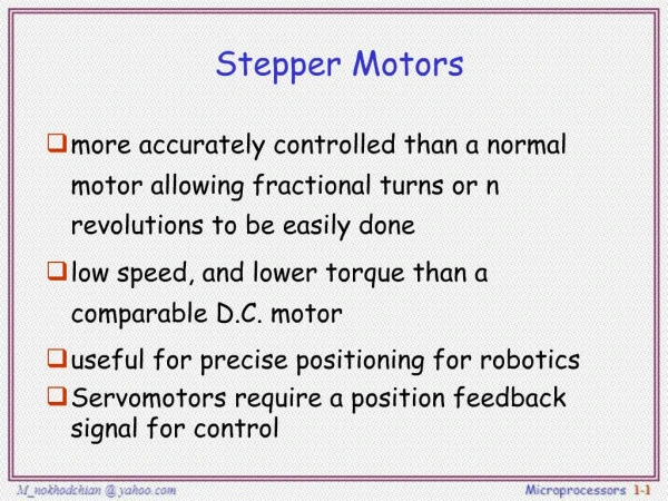
Stepper Motors • When incremental rotary motion is required in a robot, it is possible to use stepper motors • A stepper motor possesses the ability to move a specified number of revolutions or fraction of a revolution in order to achieve a fixed and consistent angular movement • This is achieved by increasing the numbers of poles on both rotor and stator • Additionally, soft magnetic material with many teeth on the rotor and stator cheaply multiplies the number of poles (reluctance motor)
Principles of operation S N Use of successive magnets
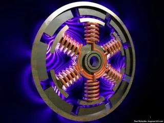
Stepper Motor Design • This figure illustrates the design of a stepper motor, arranged with four magnetic poles arranged around a central rotor • Note that the teeth on the rotor have a slightly tighter spacing to those on the stator, • this ensures that the two sets of teeth are close to each other but not quite aligned throughout
Use of successive magnets • Movement is achieved when power is applied for short periods to successive magnets • Where pairs of teeth are least offset, the electromagnetic pulse causes alignment and a small rotation is achieved, typically 1-2o
How Does A Stepper Motor Work? The top electromagnet (1) is charged, attracting the topmost four teeth of a sprocket.
How Does A Stepper Motor Work? (cont…) The top electromagnet (1) is turned off, and the right electromagnet (2) is charged, pulling the nearest four teeth to the right. This results in a rotation of 3.6°
How Does A Stepper Motor Work? (cont…) The bottom electromagnet (3) is charged; another 3.6° rotation occurs.
How Does A Stepper Motor Work? (cont…) The left electromagnet (4) is enabled, rotating again by 3.6°. When the top electromagnet (1) is again charged, the teeth in the sprocket will have rotated by one tooth position; since there are 25 teeth, it will take 100 steps to make a full rotation.
Reluctance (Stepper) Motors • angle control • slow • usually no feedback used • accurate positioning • without feedback, not servos • easy to control
Stepper Motor Types • A stepper motor can be incrementally driven, one step at a time, forward or backward • Steppermotor characteristics are: • Number of steps per revolution (e.g. 200 steps per revolution = 1.8° per step) • Max. number of steps per second (“stepping rate” = max speed) • Driving a stepper motor requires a 4 step switching sequence for full-step mode • Stepper motors can also be driven in 8 step switching sequence for half-step mode (higher resolution) • Step sequence can be very fast, then the resulting motion appears to be very smooth
Advantages of Stepper Motors • Stepper motors have several advantages: • Their control is directly compatible with digital technology • They can be operated open loop by counting steps, with an accuracy of 1 step. • They can be used as holding devices, • since they exhibit a high holding torque when the rotor is stationary
Stepper Motors Advantages and Disadvantages • Advantages • No feedback hardware required • Disadvantages • No feedback (!) Often feedback is still required, e.g. for precision reasons, since a stepper motor can “lose” a step signal. • Requires 2 H-Bridges plus amplifiers instead of 1 • Other • Driving software is different but not much more complicated • Some controllers (e.g. M68332) support stepper motors in firmware (TPU)
Electric Motors: Mounting • When used with rotary joint systems, motors can produce torque by: • being mounted directly on the joints • or by pulling on cables • The cables can be thought of as tendons that connect the actuator (muscle) to the link being moved • Since cables can apply force only when pulled, it is necessary to use a pair of cables to obtain bidirectional motion around a joint, • this implies mechanical complexity
Electric Motors: Mounting (cont…) • Mounting motors directly on joints allows for bidirectional rotation, • but such mounting may increase the physical size and weight of the joint, • and this may be undesirable in some applications
Electric Motors: Linear Movement • The fact that electric motors produce rotational motion raises an issue with regard to their use in robots • For linear translation it is necessary to translate rotational to linear motion • For example, prismatic joints require linear translation rather than rotation from the motor • Typically used to transform rotational to translational motion: • Leadscrews, • belt-and-pulley systems, • rack-and-pinion systems, • or gears and chains. Leadscrews
Motor and Encoder Motor and Encoder • Motor speed determined by: supplied voltage • Motor direction determined by: polarity of supplied voltage • Difficult to generate analog power signal (1A ..10A) directly from microcontroller → external amplifier (pulse-width modulation)
Motor and Encoder • Encoder disk is turned once for each rotor revolution • Encoder disk can be optical or magnetic • Single detector can determine speed • Dual detector can determine speed and direction • Using gears on motor shaft increases encoder accuracy
Encoder Feedback Another option: potentiometer US Digital
Pulse-Width Modulation • A/D converters are used for reading analog sensor signals • Why not use D/A converter for motor control? • Too expensive (needs power circuitry) • Better do it by software, switching power on/off in intervals • This is called “Pulse-Width Modulation” or PWM
Pulse-Width Modulation • How does this work? • We do not change the supplied voltage • Power is switched on/off at a certain pulse ratio matching the desired output power • Signal has very high frequency (e.g. 20kHz) • Motors are relatively slow to respond • The only thing that counts is the supplied power • ⇒ Integral (Summation) • Pulse-Width Ratio = ton / tperiod
Artificial Muscles • During the past forty years a number of attempts have been made to build artificial muscles • Muscles contract when activated, • since they are attached to bones on two sides of a joint, • the longitudinal shortening produces joint rotation • Bilateral motion requires pairs of muscles attached on opposite sides of a joint are required to produce
Artificial Muscles: McKibben Type • The McKibben muscle was the earliest attempt at constructing an artificial muscle • This device consisted of a rubber bladder surrounded by a sleeve made of nylon fibers in a helical weave • When activated by pressurized air, the sleeve prevented it from expanding lengthwise, and thus the device shortened like living muscles
Artificial Muscles: McKibben Type • In the 1960s there were attempts to use McKibben muscles to produce movements in mechanical structures strapped to nonfunctional arms of quadriplegics • The required compresses air was carried in a tank mounted on the person’s wheelchair • These experiments were never completely successful
Artificial Muscles: McKibben Type • Since the 1960s there has been several other attempts to develop improved McKibben type artificial muscles: • (Brooks, 1977) developed an artificial muscle for control of the arms of the humanoid torso Cog • (Pratt and Williamson 1995) developed artificial muscles for control of leg movements in a biped walking robot
Artificial Muscles: McKibben Type • However, it is fair to say that no artificial muscles developed to date can match the properties of animal muscles
Artificial Muscles: Shape Memory Alloys • Shape memory alloys (SMAs) have unusual mechanical properties • Typically, they contract when heated, • which is the opposite to what standard metals do when heated (expand) • Furthermore, they produce thermal movement (contraction) one hundred times greater than that produced by standard metals
Artificial Muscles: Shape Memory Alloys • Because they contract when heated, SMA provide a source of actuation for robots • After contraction, the material gradually returns to its original length when the source of activation is removed and it is allowed to cool • SMAs have two major problems when used as artificial muscles: • They cannot generate very large forces • They cool slowly and so recover their original length slowly, thus reducing the frequency response of any artificial muscle in which they are employed
Northeastern University’s Robot Lobster • A robot lobster developed at Northeastern University used SMAs very cleverly • The force levels required for the lobster’s legs are not excessive for SMAs • Because the robot is used underwater cooling is supplied naturally by seawater More on the robot lobster is available at: http://www.neurotechnology.neu.edu
Artificial Muscles: Electroactive Polymers • Like SMAs, Electroactive Polymers (EAPs) also change their shape when electrically stimulated • The advantages of EAPs for robotics are that they are able to emulate biological muscles with a high degree of toughness, large actuation strain, and inherent vibration damping • Unfortunately, the force actuation and mechanical energy density of EAPs are relatively low • Robotic face developed by a group led by David Hanson. More information is available at: • www.hansonrobotics.com