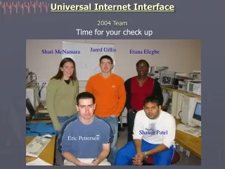
Universal Measurement System with Web Interface
Universal Measurement System with Web Interface. Maciej Lipiński Ph.D. Krzysztof Poźniak, MSc Grzegorz Kasprowicz. Warsaw 25.01 2008. Outline of the project. Hardware provided by Grzegorz Kasprowicz, consists of 3 modules:. Main module (100x80mm ): Switched-mode Power Supply

Universal Measurement System with Web Interface
E N D
Presentation Transcript
Universal Measurement System with Web Interface Maciej Lipiński Ph.D. Krzysztof Poźniak, MSc Grzegorz Kasprowicz Warsaw 25.01 2008
Outline of the project Hardware provided by Grzegorz Kasprowicz, consists of 3 modules: • Main module (100x80mm ): • Switched-mode Power Supply • Graphic controller • Sound controller • I2C interface • Peripherals: USB, RS232, Ethernet ports, output for built-in LCD-TFT and for VGA monitor • Single Board Computer module (50x70mm): • Microprocessor: ARM9 (AT91RM9200) • 128 SDRAM • Ethernet interface 10/100 Mbit • FLASH 8MB • SD/MMC reader, • Interfaces: 2 x Serial ports, 2x USB hub and device • Acquisition module: • ALTERA Cyclone I • 2 x fast, 105MS/s. 14 bit ADCs • SSRAM – 128k x 32
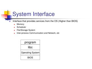
The Goal of the project: Utilization of the hardware to create an autonomous, universal measurement system with Ethernet interface and operating system on board, in order to enable on-fly reconfiguration accordingly to the user’s needs. Creation of TCP/IP and web-based control interface.
Outline of the system • The user interface will include: • Built-in LCD screen, the mouse and keyboard • www server for remote application management • Measurement server for remote measurement control (i.e.compatible with LabView environment) • Example applications: • Signal acquisition in dangerous places (i.e. high energy physics) • Signal acquisition in places which are difficult to access • Cheap, reconfigurable measurement system • Remote monitoring of industrial parameters • An element of a distributed measurement system • Digital oscilloscope LAN
Background research • Studying the provided hardware: • Thorough lecture of most important component’s datasheets • Studying hardware structure • Becoming a „good friends” with the board • Studying similar projects: • TwARM eval board - AT91RM9200 by Pelos, http://twarm.pelos.pl/ • ARM9 single board computer designed for image acquisition and processing. http://www.ime.usp.br/~fr/sbc/ • Sarge - single board compute http://www.blackmesaeast.com.pl/projects/electronics/sarge-single-board-computer/1/ • Prototype Implementation of the Embedded PC BasedControl and DAQ Module for TESLA Cavity SIMCON • Studying Linux: • Linux From Scratch by Gerard Beekmans • Kernel in a nutshell, O’Reilly • Linux Device Drivers, O’Reilly • Other background reading: • U-boot documentation: The DENX U-Boot and Linux Guide (DULG) for TQM8xxL • Many tutorials and „howto’s”
Linuxcustomized for AT91RM9200 • The system I built consists of : • Kernel: linux-2.6.22.10 • Busybox: version 1.7.2 • uClibc library: version 0.9.29 • Two kernel configurations • For the ARM microprocessor • For my computer • Cross-compiler toolchain chosen, build and used : buildroot • Kernel and root file system compiled as one image and sent to microprocessor by TFTP • Bootloader: U-boot version 1.1.4, patch from TWARM • To do: • Booting from SD/USB • NFS/booting from NFS
FPGA configuration • Binary configuration file sent by SPI • At91_spidev character device driver prepared for AT91RM9200 processor and provided in the kernel patch is used • Configuration signals controlled by mapping the PIO registers from user space • Simple program to sent configure FPGAwritten
Work to be done: • Research • Peripheral drivers • Signal processing algorithms • Protocols • Visualization techniques • Interface management • Operating System preparation • Bootable from SD/USB • Development of drivers • Appropriate components (ex. necessary server) • Reasonable size • FPGA (HDL, glue logic) • Acquisition data storage logic • SSRAM data readout logic • Signal processing algorithms implementation • Software • Programs (or drivers) development : • Data retrieval from FPGA • Data processing • Data visualization • Implementation of one of the standard measurement protocols • Create user interface: • General configuration and reconfiguration • Remote application control • Remote measurement • Direct control (LCD, mouse, Keyboard) • Tests • The system will be tested as a double channel digital oscilloscope and spectrum analyzer